16 A-Class
For proper data exchange, the serial interface requires specific cable pin-outs.
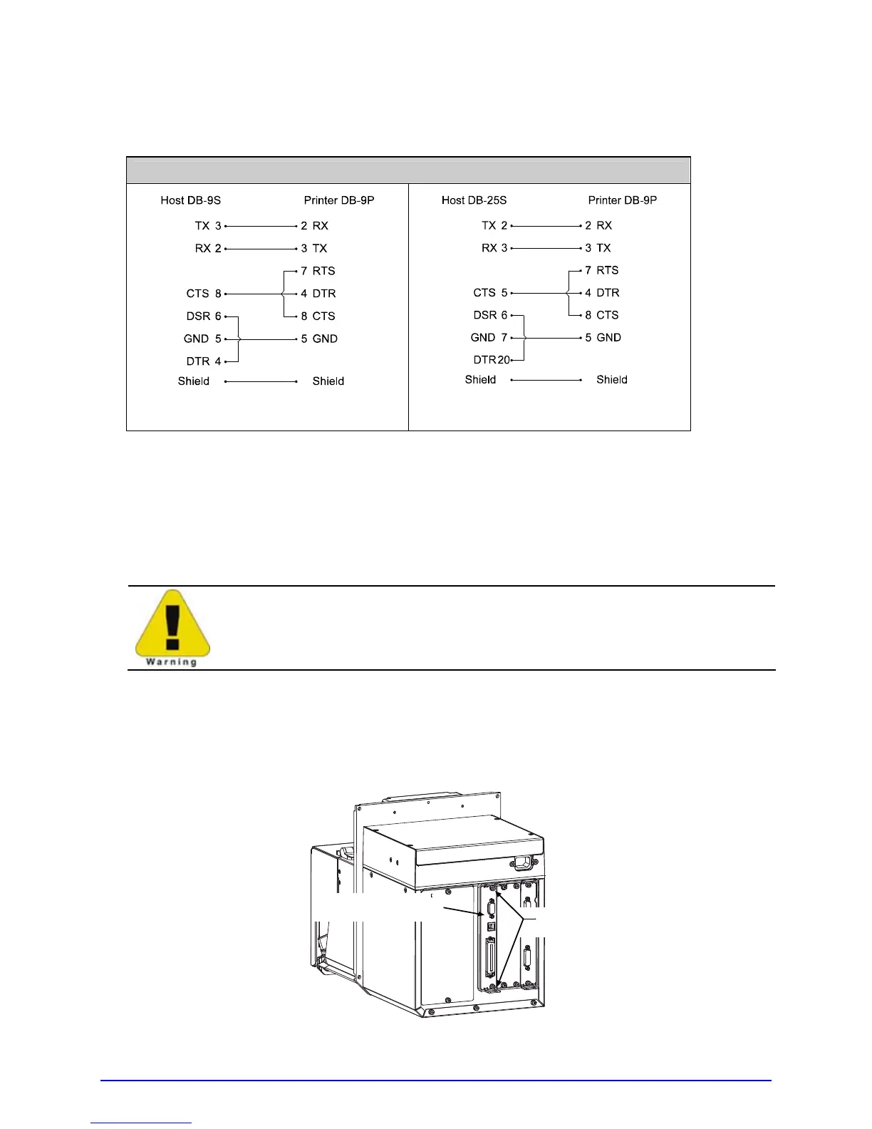
Serial cable part numbers and wiring diagrams are shown below.
RS-232 Cables*
Part # 32-2300-01
Part # 32-2301-01
*Printer serial ports A & C require a DB9 male connector (e.g., Startech C9PSM).
RS-422/485 Communications
To use RS-422/485 communications (Port A, only), the main logic card must be
reconfigured:
Always wear a wrist strap and follow standard ESD prevention measures
when handling the Main Logic Card.
1. Turn OFF the power switch, unplug the AC Power Cord from the printer, and remove
any interface cable(s) already attached to the Main Logic Card.
2. Remove the two Screws securing the Main Logic Card to the printer. Slide the card
out of the printer and place it on a static free work area.
Main Logic Card
Screws