EasyManuals Logo
Home>Datamax>Label Maker>A-Class A-6310

Datamax A-Class A-6310 User Manual

Default Icon
166 pages
To Next Page IconTo Next Page
To Previous Page IconTo Previous Page
Page #31 background imageLoading...
Page #31 background image
A-Class 17
;
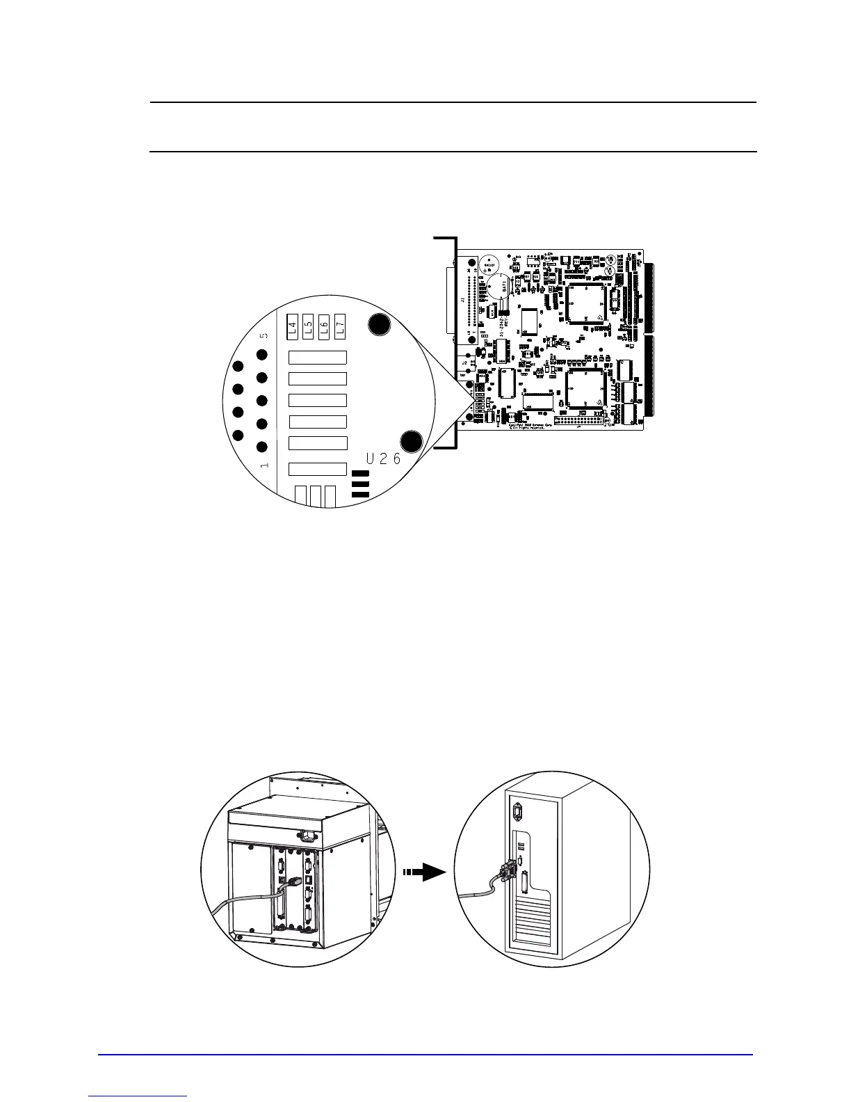
The Main Logic Card location varies depending upon the model of printer.
3. On the Main Logic Card, move the jumpers JMP1, JMP2, JMP3, JMP4, JMP5, and JMP6
from their positions across pins 1 & 2, and place them across pins 2 & 3,
respectively.
JMP 1
JMP 2
JMP 3
JMP 4
JMP 5
JMP 6
4. Replace the Main Logic Card and secure it using the previously removed screws.
5. Connect an RS-422/485 interface cable to Serial Port A (see the pin-out table,
above).
6. Plug in and turn ON the printer. Configure the port communication settings to match
that of the host.
COM D Port Connections
10101010

Table of Contents

Questions and Answers:

Question and Answer IconNeed help?

Do you have a question about the Datamax A-Class A-6310 and is the answer not in the manual?

Datamax A-Class A-6310 Specifications

General IconGeneral
BrandDatamax
ModelA-Class A-6310
CategoryLabel Maker
LanguageEnglish

Related product manuals