dCS 900E / 902E User Manual Manual for Software Versions 1.3x to 1.5x
dCS Ltd 12
th
June 2000
Manual part no: DOC0029021E1 Page 10 Document No: OS-MA-D0002-902.1E1
Contact dCS on + 44 1799 531 999 email to: more@dcsltd.co.uk
(inside the UK replace + 44 with 0) web site: www.dcsltd.co.uk
THE HARDWARE – CONTROLS AND CONNECTORS
Rear Panel
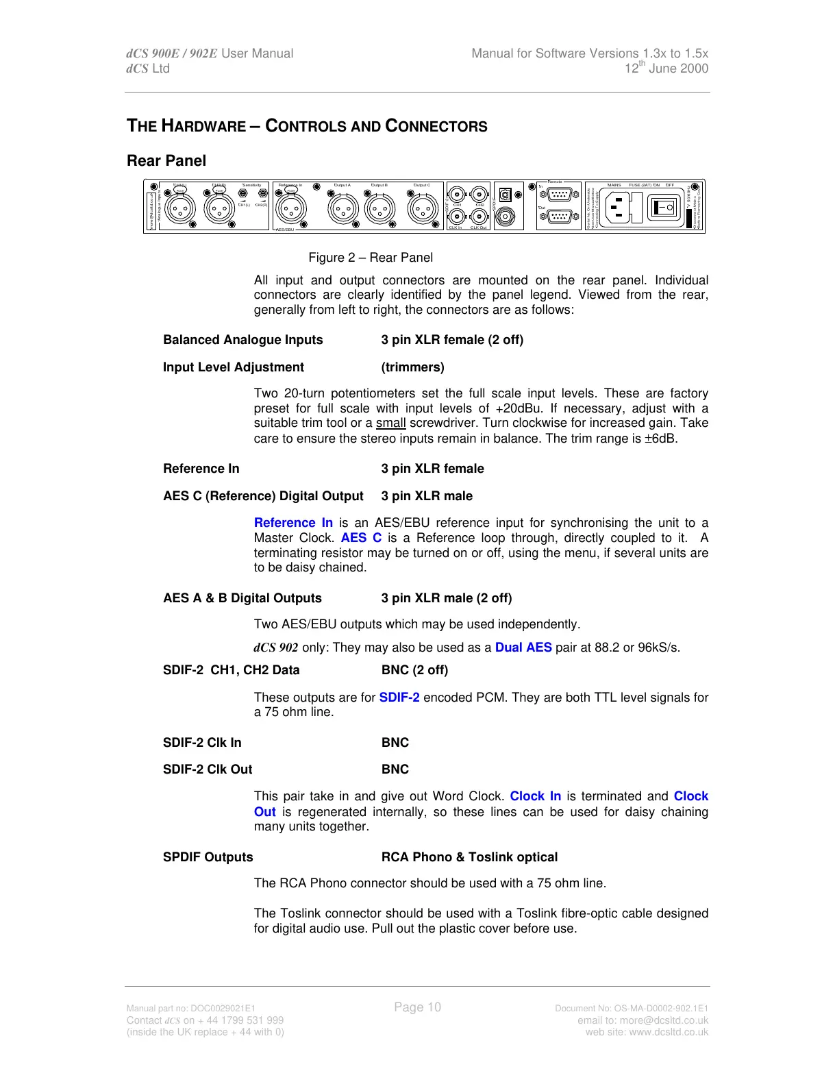
Figure 2 – Rear Panel
All input and output connectors are mounted on the rear panel. Individual
connectors are clearly identified by the panel legend. Viewed from the rear,
generally from left to right, the connectors are as follows:
Balanced Analogue Inputs 3 pin XLR female (2 off)
Input Level Adjustment (trimmers)
Two 20-turn potentiometers set the full scale input levels. These are factory
preset for full scale with input levels of +20dBu. If necessary, adjust with a
suitable trim tool or a small screwdriver. Turn clockwise for increased gain. Take
care to ensure the stereo inputs remain in balance. The trim range is ±6dB.
Reference In 3 pin XLR female
AES C (Reference) Digital Output 3 pin XLR male
Reference In is an AES/EBU reference input for synchronising the unit to a
Master Clock. AES C is a Reference loop through, directly coupled to it. A
terminating resistor may be turned on or off, using the menu, if several units are
to be daisy chained.
AES A & B Digital Outputs 3 pin XLR male (2 off)
Two AES/EBU outputs which may be used independently.
dCS 902 only: They may also be used as a Dual AES pair at 88.2 or 96kS/s.
SDIF-2 CH1, CH2 Data BNC (2 off)
These outputs are for SDIF-2 encoded PCM. They are both TTL level signals for
a 75 ohm line.
SDIF-2 Clk In BNC
SDIF-2 Clk Out BNC
This pair take in and give out Word Clock. Clock In is terminated and Clock
Out is regenerated internally, so these lines can be used for daisy chaining
many units together.
SPDIF Outputs RCA Phono & Toslink optical
The RCA Phono connector should be used with a 75 ohm line.
The Toslink connector should be used with a Toslink fibre-optic cable designed
for digital audio use. Pull out the plastic cover before use.
SPDIF
Reference In
AES/EBU
CH1(L)
Analogue Inputs
more@dcsltd.co.uk
CH2(R)
CH1(L)
Sensitivity
CH2(R)
Output BOutput A
SDIF-2
CH1 CH2
CLK OutCLK In
Output C
Remote
See User Manual Before
Connecting To Supply
Serial No. On Underside.
Out
In
MAINS ON OFF