Testing 13
Table 2–2 lists the 15 level 1 tests.
Table 2–2 Level 1 Tests
Video RAM test DUART1 timer test
Video test Keyboard port test
NVR checksum test Mouse port test
Ethernet address ROM test DUART2 timer test
Option RAM test (if present) Ethernet port (LANCE) test
Host port test Mouse test
Printer port test Keyboard test
Image test (if installed)
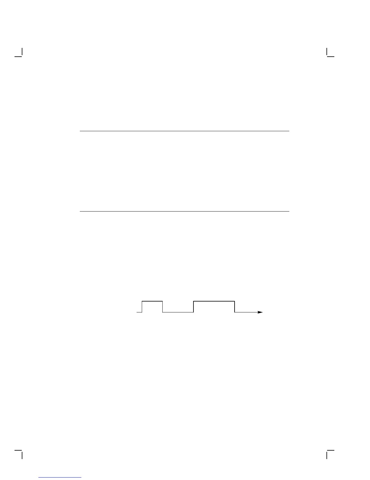
System Logic Board LED Power-Up Sequence
When the terminal powers up, the red LED on the system logic board
turns on. At the start of level 0 testing, the LED turns off. If level 0
completes successfully, the LED turns on again. The operating system
then performs level 1 testing. If level 1 testing is successful, the LED
turns off. The following diagram shows the complete sequence:
Power−Up Level 1
System
Board
LED
On
Level 0 Tests Complete
Off