Fig.5
MW-1001101-2
5
17 16 15 14 13 12 11 10 9 8 7 6
18
4 3 2 1
22
192123 20
X2 X3
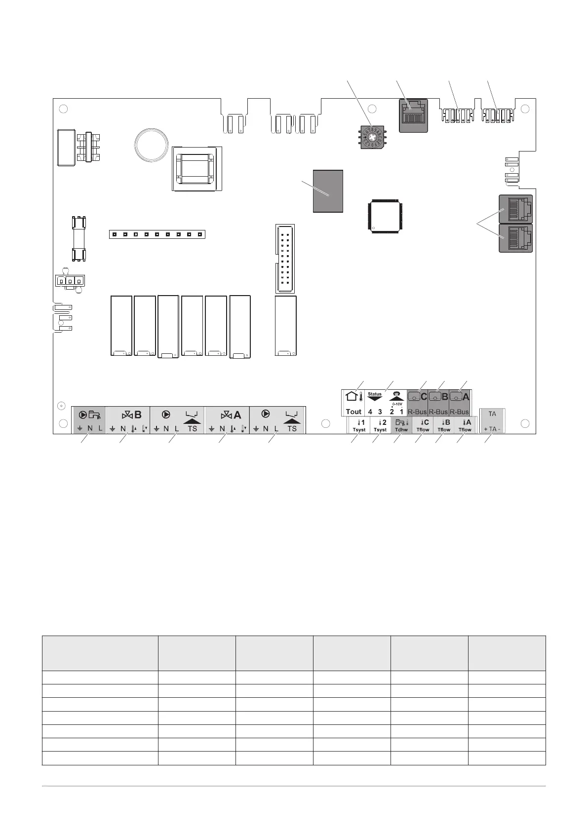
1 Room temperature sensor - circuit A
2 Room temperature sensor - circuit B
3 Room temperature sensor - circuit C
4 Programmable and 0 - 10 V input
5 Outdoor temperature sensor
6 Impressed current anode
7 Flow sensor - circuit A
8 Flow sensor - circuit B
9 Flow sensor - circuit C
10 Domestic hot water sensor
11 System sensor 2
12 System sensor 1
13 Pump and safety thermostat - circuit A
14 Three-way valve - circuit A
15 Pump and safety thermostat - circuit B
16 3-way valve - circuit B
17 Domestic hot water tank pump
18 Connectors for S-BUS cables to CB–05 PCB
19 L-BUS connection (END connector)
20 L-BUS connection to the Diematic Evolution control
panel
21 S-BUS connector to connector on the fascia
22 Mod-BUS connectors to iSystem control panel in
cascade mode
23 Coding wheel, selects the generator number in the
cascade in Mod-Bus
Tab.1 Compatibility of connections
Circuit A Circuit B Circuit C
(with AD249 op
tion)
AUX circuit
(with AD249 op
tion)
Domestic hot wa
ter circuit
Convection fan Yes Yes Yes No No
Underfloor heating Yes Yes Yes No No
Radiator Yes Yes Yes No No
365 day radiator Yes Yes Yes No No
Continuous heating Yes Yes Yes No No
Timer programme Yes Yes Yes Yes Yes
Swimming pool Yes Yes Yes No No
4 Description of the product
7703592 - v02 - 14062018 11