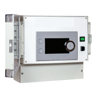
3. Connect the cable to one of the mini-DIN. sockets
4. If necessary, change the number of the generator in the cascade
using the coding wheel.
Extending a Mod-BUS cable
To increase the distance of the Mod-BUS connection, connect a 2-wire
shielded cable, use an existing AD124 bus cable with mini-DIN connector
and proceed as follows:
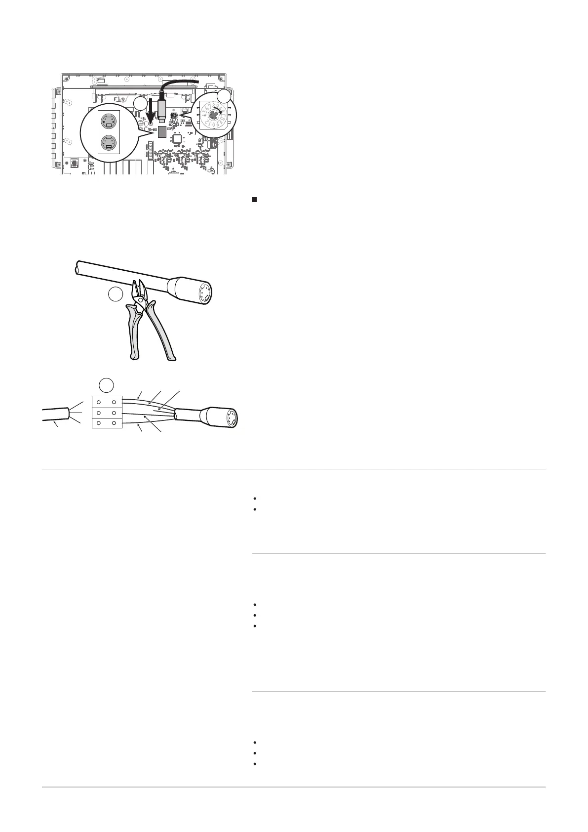
1. Cut the Mod-BUS cable
2. Connect the four wires of the BUS cable to the three pin terminal
block.
A Braided shield (0 V terminal)
B Brown wire (0 V terminal)
C Green wire (DO NOT USE)
D White wire (terminal B)
E Yellow wire (terminal A)
F 2-wire shielded cable
7.5 Selecting the operating mode
The VM Diematic Evolution box can be used:
as an extension box
as a mixed control box.
7.5.1 Using the VM Diematic Evolution box as an extension
box
In this case, the VM Diematic Evolution box is connected in a network with
one or more generators equipped with a Inicontrol-2 and Diematic
Evolution control panel (with the option of S-Bus network connection):
The circuits A, B and DHW are available as standard,
The circuits C and AUX are only available with the AD249 option,
It is possible
to have a network of 1 to 8 VM Diematic Evolution boxes or generators
equipped with a Inicontrol-2 or Diematic Evolution control panel.
7.5.2 Using the VM Diematic Evolution box as a mixed control
box
In this case, the VM Diematic Evolution box is connected in a network with
one or more generators equipped with a Diematic 4 control panel (ModBus
network connection)
The circuits A, B and DHW are available as standard,
The circuits C and AUX are only available with the AD249 option,
It is
Fig.21
Fig.22
0V B A
MW-1001115-1
B
D
CA
E
F
1
2
7 Installer instructions
28 7703592 - v02 - 14062018