possible to have from 1 to 20 Diematic VM iSystem or VM Diematic
Evolution boxes and 1 to 10 generators equipped with a Diematic 4 or
Diematic Evolution control panel.
7.6 Configuring the installation
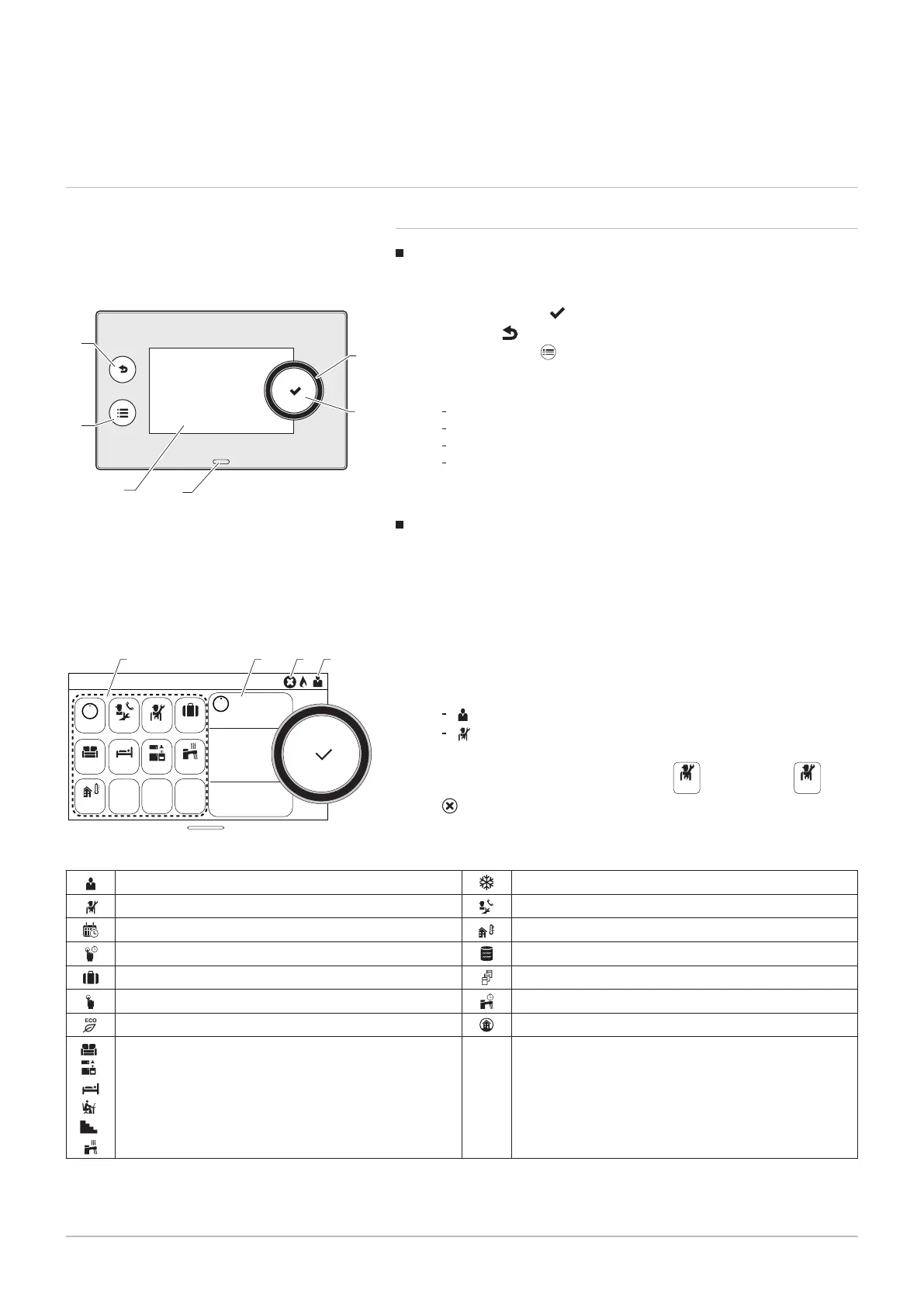
7.6.1 Control panel description
Description of the user interface
1 Rotary knob to select a menu or setting
2
Validation button
3
Back key to return to the previous level or previous menu
4
Main menu key
5 Display screen
6 LED for status indication:
continuous green = normal operation
flashing green = warning
continuous red = shutdown
flashing red = lockout
Description of the main screen
This screen is displayed automatically after the appliance is started up.
The screen goes into standby if no key is pressed for five minutes. Press
one of the buttons on the control panel to exit standby.
1 Symbols
The selected icon is highlighted.
2 Information on the selected icon
3 Navigation level:
: User level
: Installer level
This level is reserved for installers and is protected by an access
code. When this level is active, the
icon becomes
.
4
error notification: only visible if an error occurs.
Tab.17 Symbols
User Level Frost protection mode
Installer Level Maintenance message
Timer programme Outdoor temperature sensor
Timer programme override Buffer tank
Holiday mode Cascade
Manual mode Domestic hot water override
Eco mode All zones
,
,
,
,
Zone icons
Fig.23
Fig.24
MW-2000760-1
Not Set
OFF
29,4°C
29,6°C
51,2°C
6,7°C
29,4°C
None
OK
I
I
2 4 31
7 Installer instructions
7703592 - v02 - 14062018 29