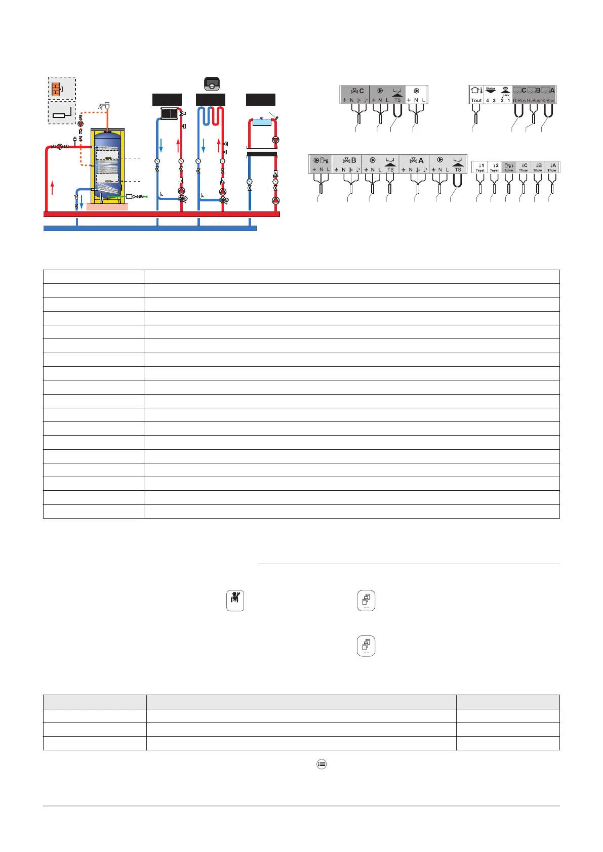
1. Make the connections on the master box.
Tab.6
1 Domestic hot water circulation loop pump
2 DHW booster pump
3 Domestic hot water temperature sensor, high position
4 Domestic hot water temperature sensor, low position
5 Flow temperature sensor after mixing valve
6 Pump for heating circuit with mixing valve
7 Three-way mixing valve
8 "Room Unit" programmable room thermostat
9 Safety thermostat with manual reset, for underfloor heating
10 Flow temperature sensor after mixing valve
11 Pump for heating circuit with mixing valve
12 Three-way mixing valve
13 Sensor for swimming pool circuit
14 Swimming pool pump
15 Automatically regulated electronic pump for direct heating circuit
16 Outdoor temperature sensor
17 Sensor for buffer tank or cascade flow
99 Bridging
2. Make the S-BUS connection to the generator.
6.2.2 System configuration
For this hydraulic configuration, certain parameters must be adapted.
1. Select the Cascade Producer Manager Algicon.
2. Select Enable master func.
3. Select Yes.
4. Select the Cascade Producer Manager Algicon.
5. Check the following parameters:
Tab.7
Code Description Adjustment required
NP006 Cascade Type Traditional
NP009 CascInterStageTime 4
NP011 CascadeTypeAlgo Temperature
6. Press the key.
7. Select Installation Setup.
Fig.10
2
1
12 7
14
3 17 4 13 10 5
MW-1001113-2
99611 9
15
16 8
999999
14
13
15
16
17
12
11
10
9
8
6
7
5
1
2
3
4
6 Connecting diagrams and configuration
18 7703592 - v02 - 14062018