01/10/2021 ASSEMBLY INSTRUCTIONS MLD Control EC-6 with CCB III Page 24
6 Connection
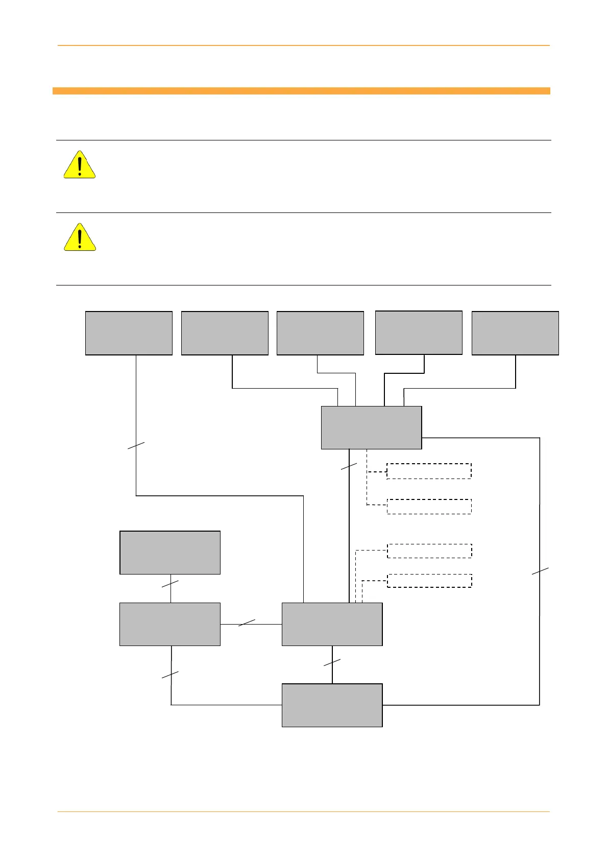
6.1 Block diagram
DANGER!
Only trained and qualified personnel may connect the EC-6 to the CCB. The EC-6 should only be
connected to the CCB when no voltage
is present.
DANGER!
The external voltage supply must meet the regional regulations. The EC-6 must be able to be
disconnected from the supply voltage by a 10 A-B or 6 A-C circuit breaker; the CCB by a 3 A-B
circuit breaker. The circuit breaker must be fully accessible.
3 x 0.5 mm²
or
3 x 1 mm²
4 x 0.5 mm²
2 x 0.5 mm²
3 x 1 mm²
2 x 1 mm²
This diagram is an example. The wire cross section has to be dimensioned according to the cable length and
to the local requirements.
Evaluation unit
Wind monitor
4 x 0.5 mm² or
8 x 0.5 mm²