01/10/2021 ASSEMBLY INSTRUCTIONS MLD Control EC-6 with CCB III Page 9
2.2 EC-6: Function
Priorities in operation: 1. Only one motor can be active (either AZ or EL), never both at the same time.
2. MLD sensors: AZ has priority over EL.
3. External inputs have priority over MLD sensors.
4. External EL input has priority over external AZ.
Reverse polarity function:
This function is used to make sure the module surface is within the transmission range of the MLD sensors in
any weather situation.
The reverse polarity function becomes activated when the same signal has been present at inputs 13-14 of
EC-6 for longer than 7 minutes. The reverse polarity function remains active for 6 minutes. Signals from the
MLD sensors are ignored during this time. The external inputs, joystick, broken wire detection and wind
monitor have priority. Jumpers can be used to deactivate the reverse polarity function.
Reverse direction function:
This function ensures the module surfaces are facing east the next morning to receive the first rays of
sunlight.
The AZ motor will switch on for 12 minutes once the EC-6 has not registered a signal at inputs 11-12 and 13-
14 for more than 4 hours. In the northern hemisphere, the system must rotate to the south; in the southern
hemisphere, it must rotate to the north. Either jumper J3 or J4 must be connected for this function.
The external inputs, joystick, broken wire detection, MLD sensors and wind monitor have priority. Jumpers
can be used to deactivate the reverse direction function.
SAFE POS (broken wire detection) function:
This function is used to compensate for any possible malfunctions (e.g., cable interruptions).
Continuous voltage of DC 24 V must be present at EC-6 inputs 20-21 for the control to function normally.
The EL motor output will be controlled continuously if the voltage signal is interrupted. The module surface
will move into the SAFE POS (table position). The SAFE POS output has top priority.
Jumpers can be used to deactivate the SAFE POS function.
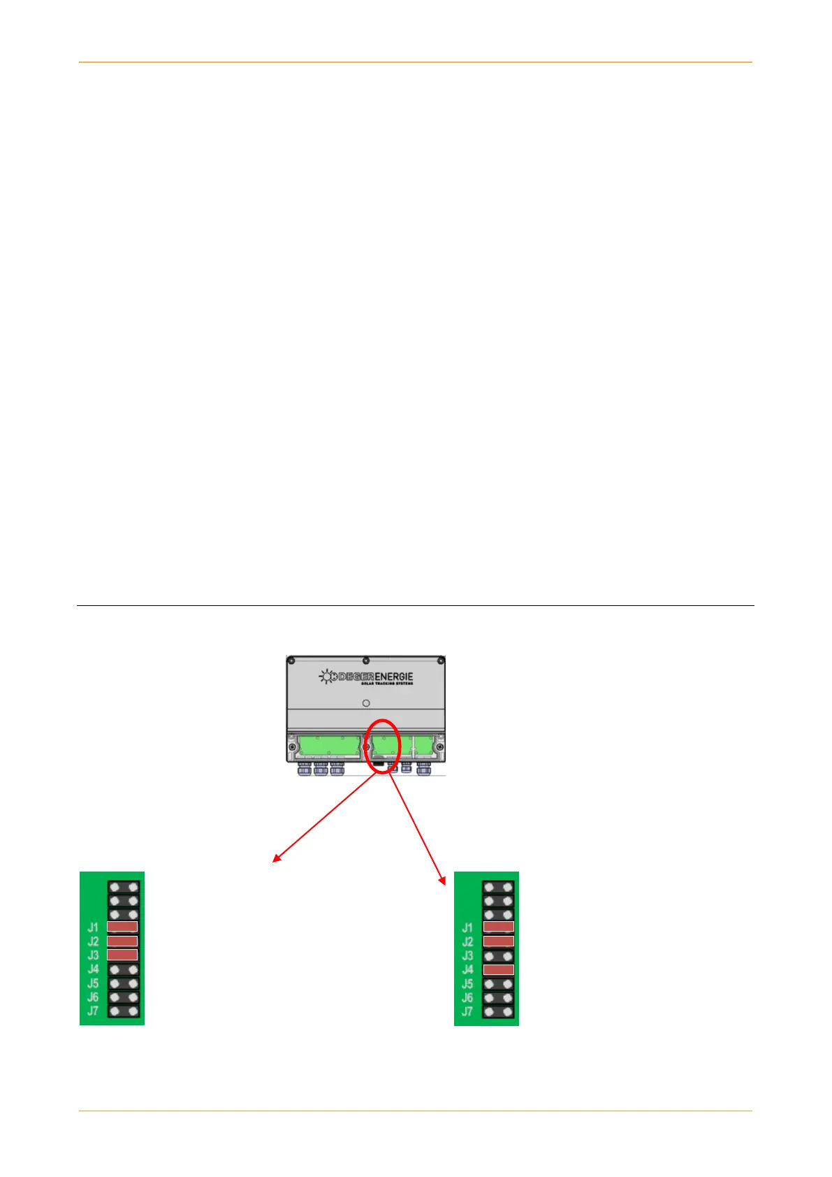
2.3 EC-6: Default setting
Delivery for southern hemisphere: Delivery for northern hemisphere:
Jumpers J1, J2 and J3 are connected. Jumpers J1, J2 and J4 are connected.
J1: Reverse polarity ON J1: Reverse polarity ON
J2: SAFE POS function OFF J2: SAFE POS function OFF
J3: Reverse direction for southern hemisphere ON
J4: Reverse direction for northern
hemisphere ON
Jumper J2 must be connected to J7 for broken wire detection to be activated.