01/10/2021 ASSEMBLY INSTRUCTIONS MLD Control EC-6 with CCB III Page 8
2 Energy Converter 6 (EC-6)
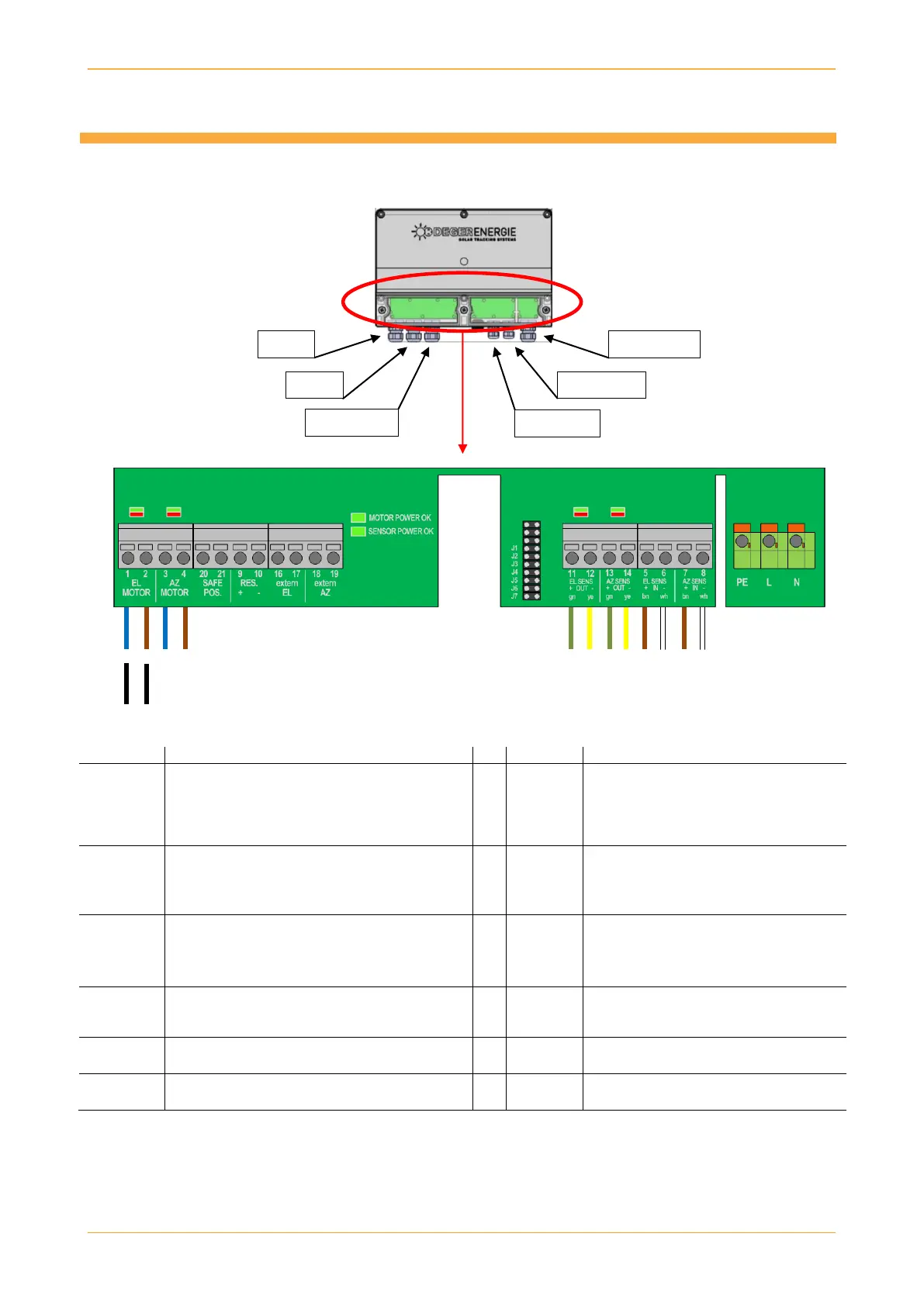
2.1 EC-6: Pin assignment
or
2 1
The clamping area on the M12 cable fitting is designed for a cable cross-section of 1 to 5 mm, while the
clamping area on the M16 cable fitting is designed for a cable cross-section of 2 to 7 mm.
Output EL Motor DC 24 V
Terminal 1 => Blue wire or wire 2, depending
on motor
Terminal 2 => Brown wire or wire 1, depending
on motor
Output MLD sensor for EL
Terminal 11 => Green wire
Terminal 12 => Yellow wire
Output AZ motor, DC +/-24 V
Terminal 3 => Blue wire
Terminal 4 => Brown wire
Output MLD sensor for AZ
- DC +/-23 V
Terminal 13 => Green wire
Terminal 14 => Yellow wire
Input SAFE POS (broken wire detection)
- DC +/-21 V
- DC +/-21 V
Input MLD sensor for EL
Terminal 5 => Brown wire DC +24 V
Terminal 6 => White wire DC 0 V
Output reserve DC 24 V, max. 1.1 A
Input MLD sensor for AZ
Terminal 7 => Brown wire DC +24 V
Terminal 8 => White wire DC 0 V
Input external EL from CCB
Input supply voltage
- AC 100 to 240 V
Input external AZ from CCB