01/10/2021 ASSEMBLY INSTRUCTIONS MLD Control EC-6 with CCB III Page 25
6.2 Connection diagram
ATTENTION!
The external voltage supply must meet the regional regulations. EC-6 and CCB devices must be
able to be disconnected from the supply voltage by a 10A B or 6A C circuit breaker. The circuit
breaker must be fully accessible.
ATTENTION!
Do not change the default settings. Changing the default values will void any existing warranty.
1. Open the housing cover for the CCB and EC-6.
2. A 4-wire data cable is suitable for the simple connection of EC-6 to CCB.
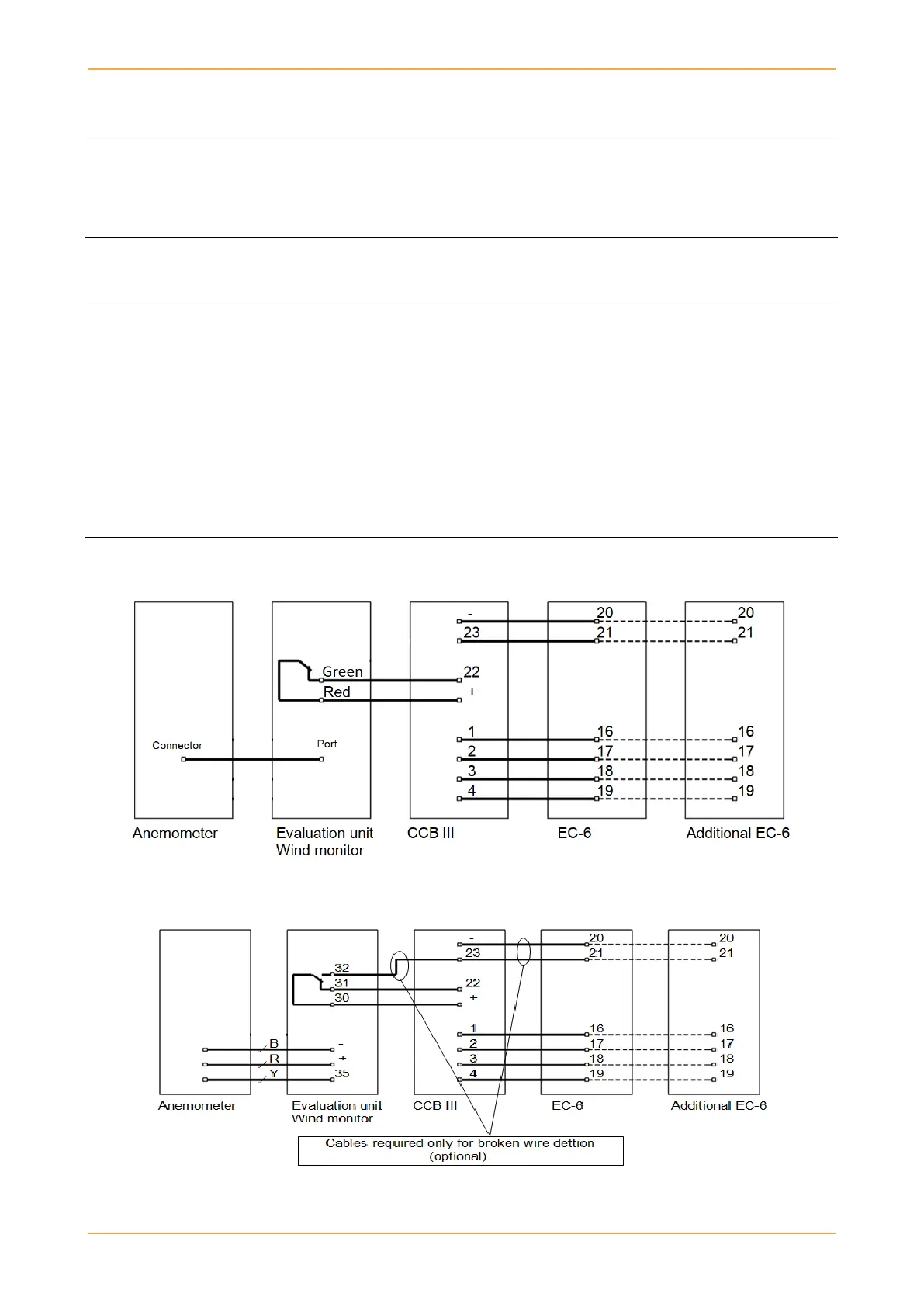
3. A 6-wire cable is required when the SAFE POS (broken wire detection) is integrated.
4. Use conductor cross-section for control cable EC-6 to CCB: For each DEGER system (EC-6) 10 mA at
DC 24 V
5. An uninterruptible power supply (UPS) is strongly recommended to bring the module surface into
horizontal position during a power failure. The UPS must be able to supply each DEGER system with
50W for at least 15 minutes. Furthermore the UPS has to be designed for the local environmental impacts
and legal regulations. There is no need for a potential free contact if the UPS is only connected to the
EC-6 (not to the CCB!) and the broken wire detection (function SAFW POS) is activated.
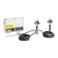
6.2.1 CCB III with wind monitor
6.2.2 CCB III with old wind monitor
Note: B: Black, R: Red & Y: Yellow