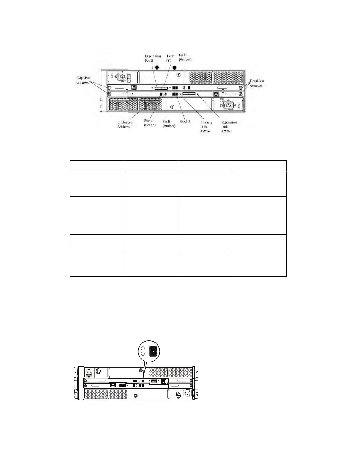
Figure 8 Rear panel overview
Table 3 Status LEDs
Light Quantity Color Meaning
Controller power 1 per controller Green On when the
controller is powered
on
Controller failure 1 per controller Amber On when either the
controller or a SAS
connection has failed.
On during a power-on
self test.
Host link active 1 per controller Blue On when the host
connection is active
Expansion link active 1 per controller Blue On when the
expansion host is
active
Removing an LCC
This procedure describes how to remove an LCC from the DAE.
Before you begin
Identify the faulted LCC by its amber fault LED.
Figure 9 LCC fault LED
Removing and replacing FRUs
Dell EMC ES40 Expansion Shelf Guide Field Replacement Unit Guide 23