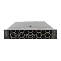
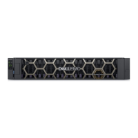
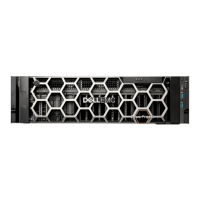
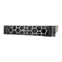
Figure 28. LEDs: Ops panel—2U enclosure front panel
Table 4. Ops panel functions (see left ear on 2U front panel)
No. Indicator Status
1 System power Constant green: at least one PCM is supplying power
O: system not operating regardless of AC present
2 Status/Health
Constant blue: system is powered on and controller is ready
Blinking blue (2 Hz): Enclosure management is busy
Constant amber: module fault present
Blinking amber: logical fault (2 seconds on, 1 second o)
3 Unit identication display Green (seven-segment display: enclosure sequence)
4 Identity
Blinking blue (0.25 Hz): system ID locator is activated
O: Normal state
System power LED (green)
LED displays green when system power is available. LED is o when system is not operating.
Status/Health LED (blue/amber)
LED illuminates constant blue when the system is powered on and functioning normally. LED blinks blue when enclosure management is
busy, for example, when booting or performing a rmware update. LEDs helps you identify which component is causing the fault. LED
illuminates constant amber when experiencing a system hardware fault which could be associated with a Fault LED on a PCM or IOM. LED
illuminates blinking amber when experiencing a logical fault.
Unit identication display (green)
The UID is a dual seven-segment display that shows the numerical position of the enclosure in the cabling sequence. This is also called the
enclosure ID. The controller enclosure ID is 0.
Storage system hardware
23

 Loading...
