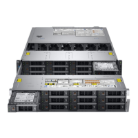
Figure 139. Installing the 2.5 inch drive rear backplane
Next steps
1. Install all the drives.
2. Connect all the cables to the backplane.
3. Follow the procedure listed in After working inside your system.
Cable routing
Figure 140. Cable routing – 24 x 2.5 inch drive backplane with mini PERC
1.
backplane 2. backplane signal cable (BP: BPSIG1 to MB: BPSIG1)
3. backplane power cable A (BP: BP1 to MB: BP1) 4. backplane power cable B (BP: BP3 to MB: BP3)
5. system board 6. mini PERC
7. SAS cable (BP: PE1_B to mini PERC) 8. backplane expander
Installing and removing system components 181
 Loading...
