8. Remove the rear I/O-cover.
9. Remove the system board Mylar.
About this task
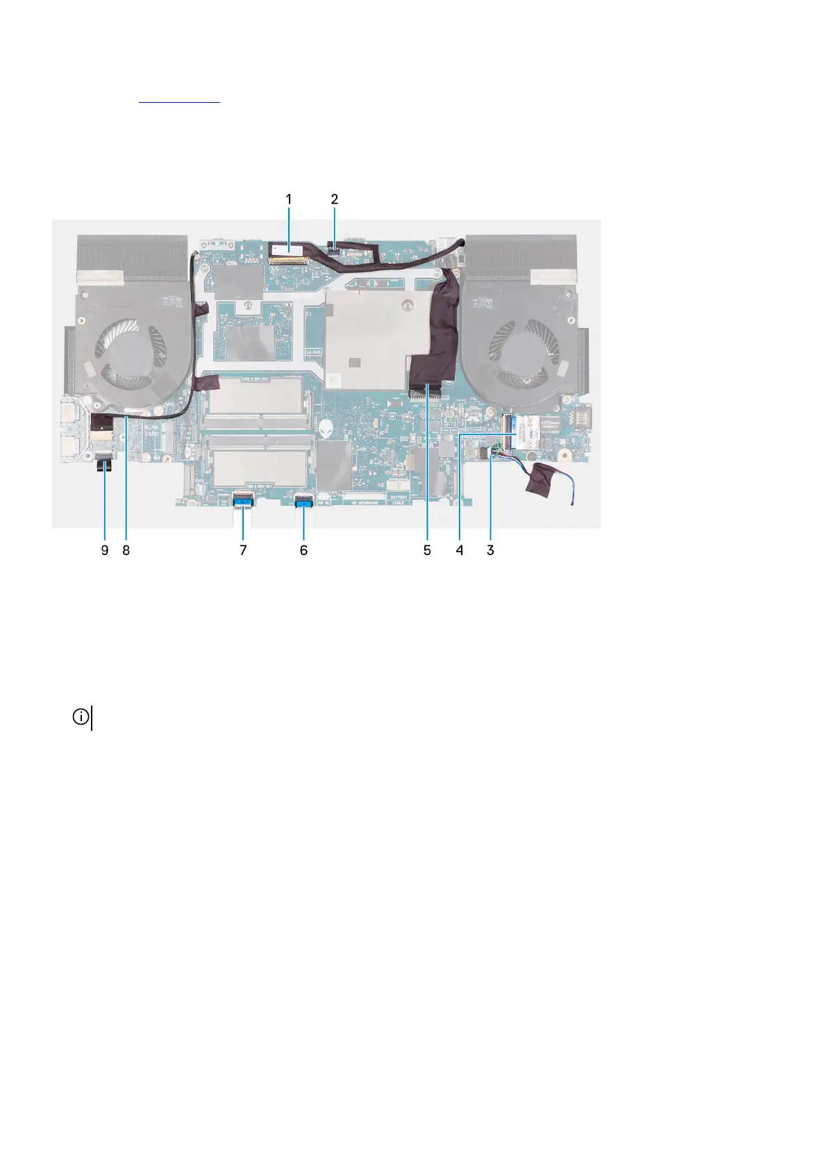
The following image indicates the connectors on your system board.
1. Display cable
2. Alienhead LED cable
3. Speaker cable
4. I/O-board cable
5. Power-adapter port cable
6. Touchpad cable
7. Keyboard-controller board cable
8. RGB-IR camera cable
NOTE: This applies to devices that are shipped with a hybrid RGB-IR camera module.
9. Power-button board cable
The following image indicates the location of the system board and provides a visual representation of the removal procedure.
58