Steps
1. Disconnect the rear I/O board cable from the connector on the system board.
2. Peel the tapes securing the rear I/O board cable to the system board.
3. Peel the tape securing the camera cable to the system board.
4. Open the latch and disconnect the camera cable from the connector (CAM1) on the system board.
5. Peel the tape that secures the display-cable connector latch to the system board.
6. Open the latch and disconnect the display cable from the connector (LCD1) on the system board.
7. Turn the computer over.
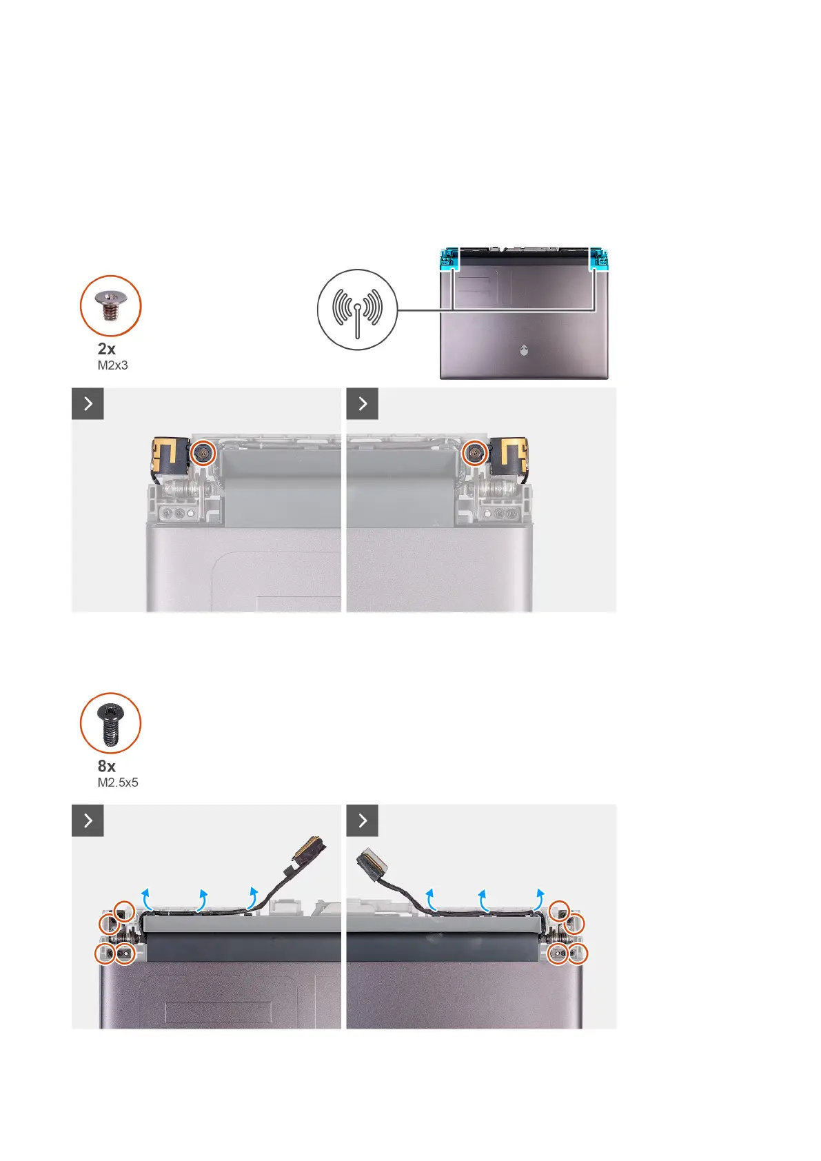
8.
Remove the two screws (M2x3) that secure the antenna holder to the display assembly.
9. Slightly move the antenna holder to make the screws on the display hinges accessible.
10.Peel the display cable off the system board and remove the display cable from the slot on the palm-rest and keyboard assembly.
70