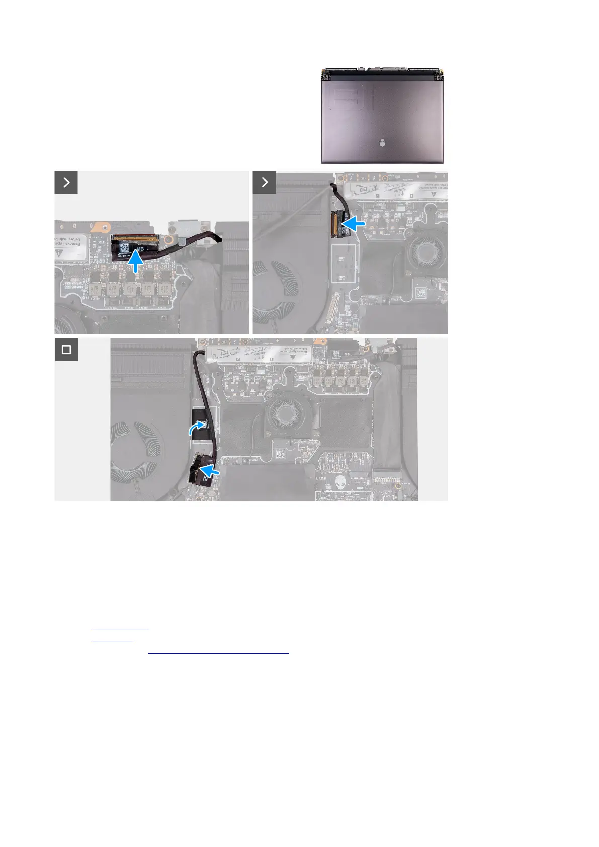
8. Adhere the display cable to the system board.
9. Connect the display cable to the connector (LCD1) on the system board and close the latch to secure the cable.
10.Adhere the tape that secures the display-cable connector latch to the system board.
11. Connect the camera cable to the connector (CAM1) on the system board.
12. Adhere the tape securing the rear I/O board cable to the system board.
13. Connect the rear I/O board cable to the connector on the system board.
Next steps
1. Install the
rear I/O cover.
2. Install the base cover.
3. Follow the procedure in After working inside your computer.
System board
System board overview
The following image indicates the connectors on your system board.
74