Steps
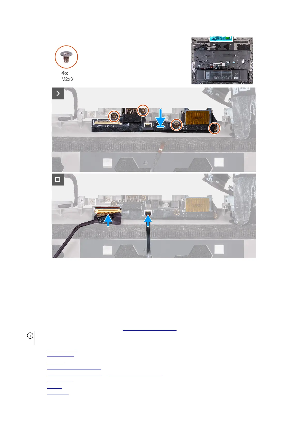
1. Align the screw holes on the I/O board with the screw holes on the palm-rest and keyboard assembly.
2. Replace the four screws (M2x3) that secure the I/O board to the palm-rest and keyboard assembly.
3. Connect the rear I/O board cable to the connector on the I/O board and close the latch.
4. Adhere the tape securing the I/O board cable to the I/O board.
5. Connect the power-button cable to the connector on the I/O board and close the latch to secure the cable.
Next steps
1. Follow the procedure from step 5 to step 25 in
Installing the system board.
NOTE: The system board can be removed and installed along with the heat sink. This simplifies the removal and installation
procedure and avoids breaking the thermal bond between the system board and heat sink.
2. Install the rear I/O cover.
3. Install the top heat-sink.
4. Install the small fan.
5. Install the M.2 2230 solid-state drive in slot three and four, if applicable.
6. Install the M.2 2280 solid-state drive or M.2 2230 solid-state drive in slot one and two, whichever is applicable.
7. Install the wireless card.
8. Install the battery.
9. Install the
base cover.
93