Steps
1. Align and replace the system board into the palmrest assembly.
2. Replace the single M2x2.5 screw securing the system board to the palmrest assembly.
3. Replace the USB Type-C bracket on the system board and secure it using the three M2x5 screws.
4. Connect the following cables:
• IR camera cable (for systems shipped with IR camera)
• Touchscreen cable (for systems shipped with touchscreen)
• Display cable
• Sensor daughterboard cable
• Touchpad FFC
• Battery LED FPC
• USH daughterboard FFC
5. Replace the eDP bracket on the display cable connector of the system board and replace the two M2x2 screws securing it to the
system board.
6. Re-route the antennae cable on the system board.
7. Replace the four M2x3.5 screws securing the F-beam FPC to the I/O board.
Next steps
If you are replacing a component, remove the existing component before performing the installation procedure.
1. Install the:
a. Heatsink assembly
b. WLAN antennae bracket
c. Solid state drive
d. Battery
e. Base cover
2. Follow the procedure in After working inside your computer.
Keyboard
Removing the keyboard
Prerequisites
1. Follow the procedure in Before working inside your computer.
2. Remove the:
a. Base cover
b. Battery
c. WLAN antennae bracket
d. Heatsink assembly
e. I/O Board
f. System board
NOTE: System board can be disassembled without having to remove the heatsink assembly.
3. Loosen and remove the single M2x2 screw on the SSD thermal shield and remove the system board shield.
About this task
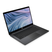
The following images indicate the location of the keyboard and provide a visual representation of the removal procedure.
Removing and installing components
43
 Loading...
