System Board: Dell Latitude E4300 Service Manual
file:///C|/Biz%20Client/2015/Lola%20(Defect%20Fix)/sysboard.htm[5/25/2015 11:14:16 AM]
www.dell.com at: www.dell.com/regulatory_compliance.
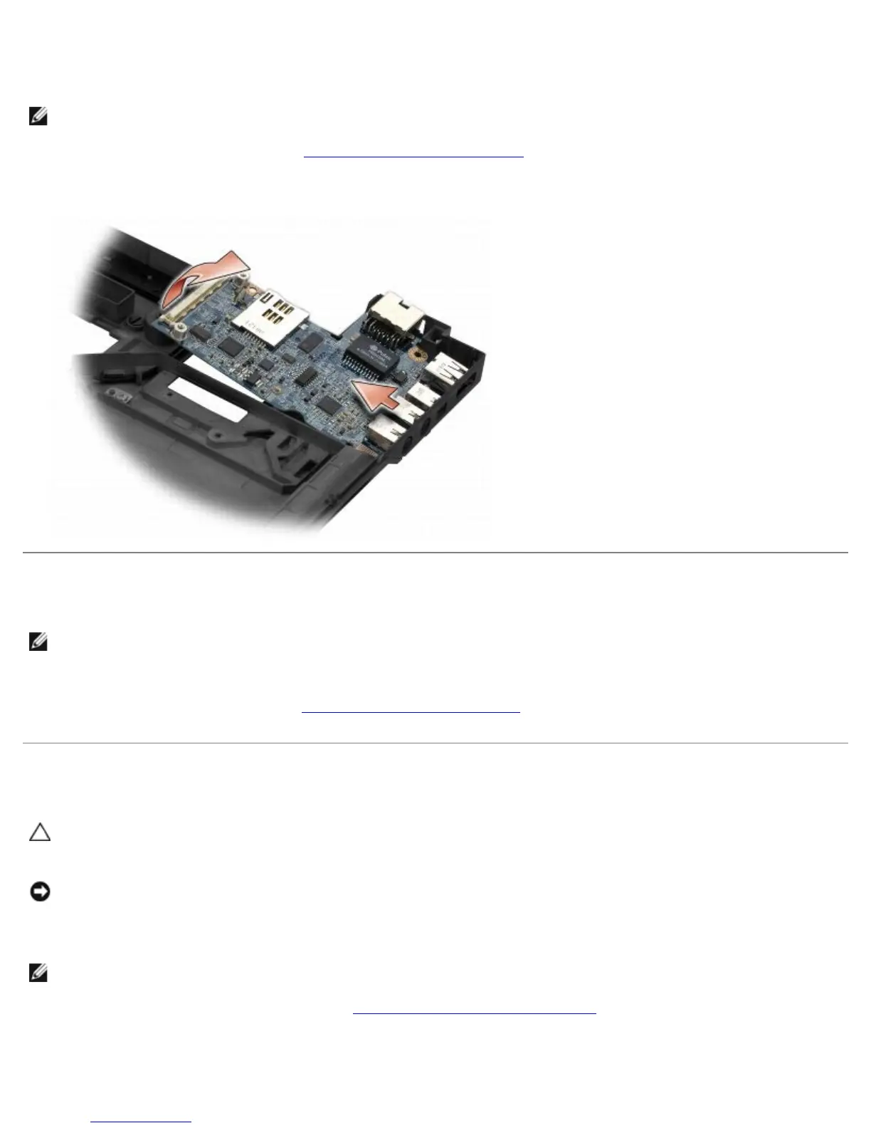
The right I/O card provides USB, audio, and IEEE 1394 connectors for the computer.
NOTE: This procedure assumes that you have completed the system board removal procedure first.
1. Remove the radio switch board (see Removing the Radio Switch Board
).
2. Use a scribe under the left side of the I/O card to lift the card from the computer.
Replacing the Right I/O Card
NOTE: This procedure assumes that you have completed the right I/O card removal procedure first.
1. Reseat the right I/O card, aligning the connectors with their respective ports on the right side of the computer base.
2. Replace the radio switch board (see Replacing the Radio Switch Board).
Removing the Left I/O Card
CAUTION: Before working inside the computer, read the safety information that shipped with the
computer. For additional safety best practices information, see the Regulatory Compliance Homepage on
www.dell.com at: www.dell.com/regulatory_compliance.
NOTICE: If you are replacing the system board assembly, retain the DC-in power assembly. The DC-in
power assembly is not included with the replacement system board assembly.
The left I/O card provides DC-in, video, and USB connectors.
NOTE: This procedure assumes that you have completed the system board removal procedure first.
1. Remove the DC power-cable assembly (see Removing the DC-In Power Assembly
).
2. Remove the M2.5 x 5-mm screw securing the left I/O card to the computer base.
3. Remove the left I/O card from the computer.