19. Remove the two screws (M2x3) that secures the USB Type-C bracket to the system board and palm-rest and keyboard assembly.
20. Disconnect the power-adapter port cable from the system board.
21. Using the pull tab, disconnect the display cable from the system board.
22. Remove the two screws (M2x2) that secures the system board to the palm-rest and keyboard assembly.
Installing the system board
Prerequisites
If you are replacing a component, remove the existing component before performing the installation procedure.
About this task
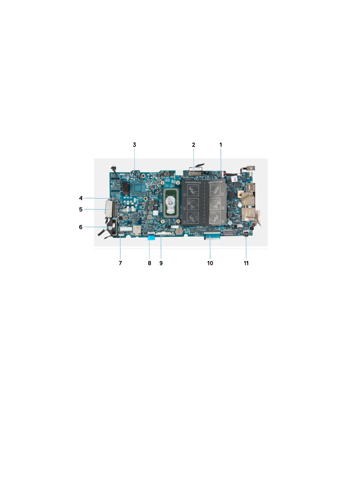
The following image indicates the connectors on your system board.
Figure 2. System-board connectors
1.
Power-adapter port cable 2. Display cable
3. Pen-garage cable 4. Fan cable
5. Touchscreen cable 6. I/O board cable
7. Speaker cable 8. Touchpad cable
9. Battery cable 10. Keyboard cable
11. Keyboard backlit cable
The following image indicates the location of the system board and provides a visual representation of the installation procedure.
52
Removing and installing components