Description
file:///T|/htdocs/stor-sys/ML6000/en/html/ch02.htm[9/17/2012 1:49:17 PM]
1 LEDs (blue, amber, green)
2 Gigabit Ethernet (external network) port
3 Ethernet I/O blade control ports (inactive if FC I/O blades are not installed)
4 Service Ethernet port
5 Service serial port
Fibre-Channel input/Output Blades
9U Library Expansion Modules support optional Fibre Channel (FC) input/Output (I/O) blades that provide connections for FC
tape drives in the library. Each FC I/O blade has an embedded controller that provides connectivity and features that enhance
the performance and reliability of tape drive operations. I/O blades also aggregate FC tape drive connections, reducing switch
port and cabling requirements.
Each FC I/O blade has six auto-negotiating, 4 Gb/s FC ports and backplane connections. The FC I/O blade provides two host
communication ports and four connection ports to FC drives. Each FC I/O blade is cooled by a fan blade that is installed next
to the FC I/O blade in the 9U Library Expansion Module. FC I/O blades and fan blades are hot-swappable.
FC I/O blades cannot be installed in the 5U Library Control Module, so your library configuration must include at least one
9U Library Expansion Module to include FC I/O blades. Each 9U Library Expansion Module can house up to two FC I/O blades.
Depending on the number of installed 9U Library Expansion Modules, the library can support from one to four FC I/O blades.
No library configuration can contain more than four FC I/O blades. Any FC drive in the library, including drives in the
5U Library Control Module, can be connected to an FC I/O blade in a 9U Library Expansion Module.
Note: FC I/O menu commands are available for use only when FC I/O blades are installed in the library.
The FC I/O blade indicates its status with three LED status indicators. These indicators are green, amber, and blue in color.
• Green represents processor status.
• Amber represents health status.
• Blue represents power-control status.
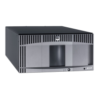
Figure 9 shows the FC I/O Blade, including LEDs. For more information on the behavior of the FC I/O Blade LEDs, see LCB
and FC I/O Blade LEDs.
For information on configuring I/O blades, see Working With FC I/O Blades.
 Loading...
