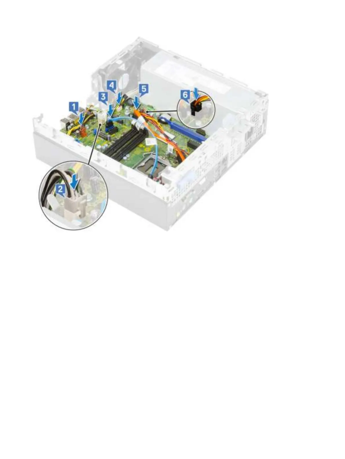
4 Align the cables with the pins on connectors on the system board and connect intrusion switch cable [1], PSU power cable [2], data
cable [3], system fan cable [4], SATA cable [5], SATA power cable [6] to the system board:
5 Insert the hook on the I/O panel into the slot on the chassis and rotate to close the I/O panel [1].
6 Replace the screw to secure the I/O panel to the chassis [2].
7 Connect the power switch cable [3], route the power cable through the retention clips on the chassis [4], psu cable [5] and, intrusion
switch cable [6] from the connectors on the system board.
Removing and Installing components 79