Chapter 8 Load Cell Module AS02LC
8- 3
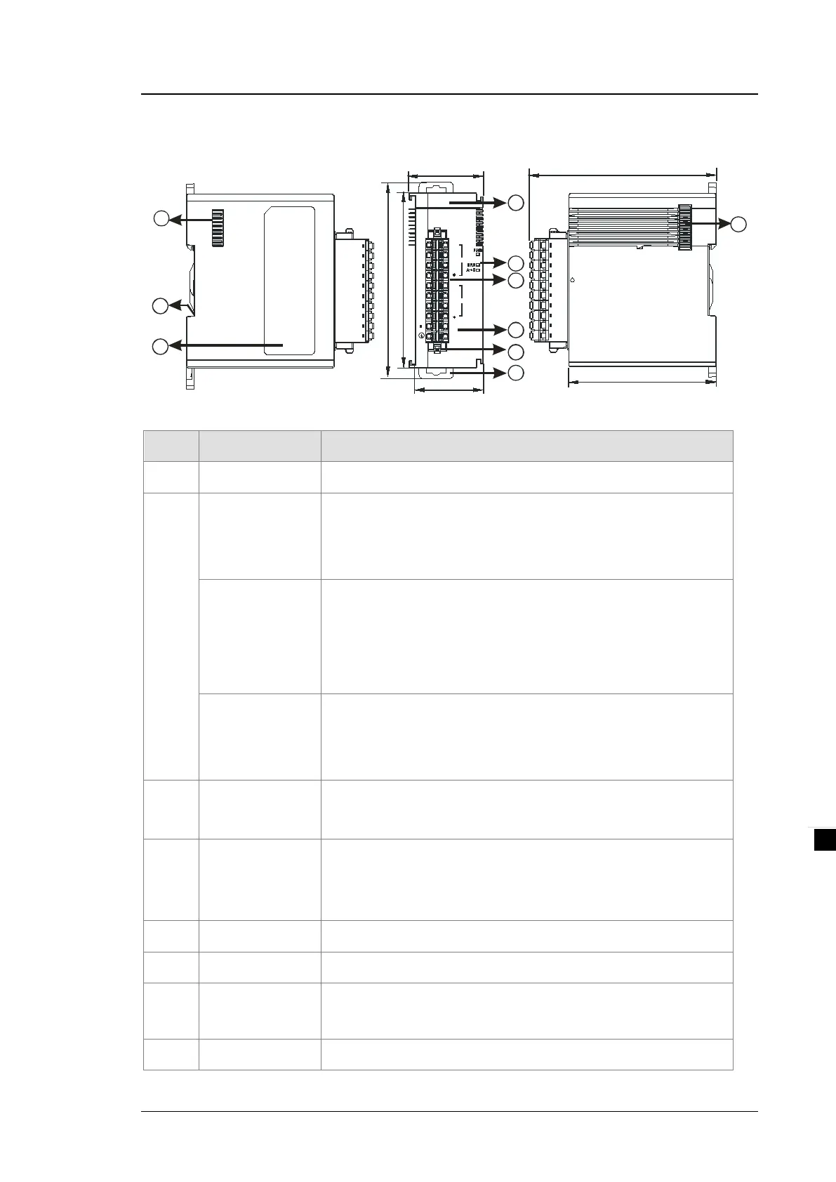
8.2.2 Profile
38.2
35
88
98.3
1
4
5
2
3
6
EX C
-
EX C+
SLD
0V
2 4V
SE N+
EX C+
SIG +
SE N+
SLD
SIG +
CH2
SE N
-
EX C
-
SIG
-
CH1
SE N
-
SIG
-
02LC
7
8
9
95
75
7
Unit: mm
Number
Name Description
1 Model Name Model name of the module
2
RUN LED Indicator
Operating status of the module
ON: the module is running.
OFF: the module is not running.
ERROR LED
Indicator
Error status of the module
ON: a serious error exists in the module.
OFF: the module is operating normally.
Blink: a minor error exists in the module.
Analog-to-Digital
Conversion
Indicator
Conversion status
Blinking: conversion is in process.
OFF: conversion has stopped.
3
Removable
Terminal Block
The inputs are connected to transducers.
The outputs are connected to loads to be driven.
4
Arrangement of the
Input/Output
Terminals
Arrangement of the terminals
5 Clip For removing the terminal block
6 DIN Rail Clip Secures the module onto the DIN rail
7
Module Connecting
Set
Connects the modules
8 Ground Clip
 Loading...