AS Series Module Manual
14-12
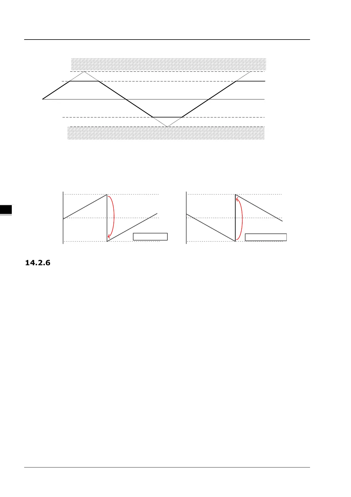
0
2,147,483,647
-2,147,483,648
Maximum
counter value
Minimu m
counter value
Linear counter
overflow
Linear counter
underflow
4. Ring counter overflow/underflow detection
Enable the Ring Counter Overflow/Underflow Detect function in the Alarm Setting of HWCONFIG.
When the overflow or underflow occurs, the alarm will appear.
Ring counter
ove rflow
2
31
-1
-2
31
0
Counter
value
2
31
-1
-2
31
0
Ring
c
ounter
under
flow
Counting
up
Counting down
SSI Input Counting
To perform the SSI input counting, first set the configuration of channels in HWCONFIG which includes encoder coding
method, clock rate, SSI data format, monoflop time and maximum variation limit. After the configuration setting is completed,
use the API instruction DHCCNT which is special for AS02HC-A in a program to obtain the counting value, achieve the
counter control as well as get the real time counter state.
1. Encoder Coding Method
There are two coding methods, Binary Code and Gray Code for SSI absolute encoder. The Binary Code is the
default coding method. If the Gray Code is selected, the gray-code position data (multi-turn and single-turn data)
transmitted back from the SSI encoder will be converted into the binary-code position data.
2. Clock Rate
The HWCONFIG software provides 5 clock rates for option including 250 kHz, 500 kHz, 625 kHz, 1 MHz and 1.25
MHz. Default: 1 MHz.
3. SSI Data Format
Set Multi-turn, Single-turn and Status Data start bit & length as well as Parity Check based on the specifications of
the used SSI absolute encoder. For SSI data format, 12ST, 13ST, 12 MT+13ST and User-Defined are provided for
option. See the descriptions as below for details.
 Loading...