AS Series Module Manual
11-28
Configure the DeviceNet network by following the steps above. The IO data mappings between
AS01DNET-A and the slave are shown in the following tables.
AS01DNET-A → Slave
AS PLC
AS01DNET(Master) AS01DNET(Slave) AS PLC
D26105
D26000
D26106 D26001
D26107 D26002
D26108 D26003
Slave → AS01DNET-A
AS PLC
AS01DNET(Master) AS01DNET(Slave) AS PLC
D26005
D26100
D26006 D26101
D26007 D26102
D26008 D26103
Saving configuration data
Select File>> Save to save current network configuration.
11.4.7.3. DeviceNet Network Control
This section describes how to write a ladder program to achieve the control requirement of the DeviceNet network.
PLC Programs
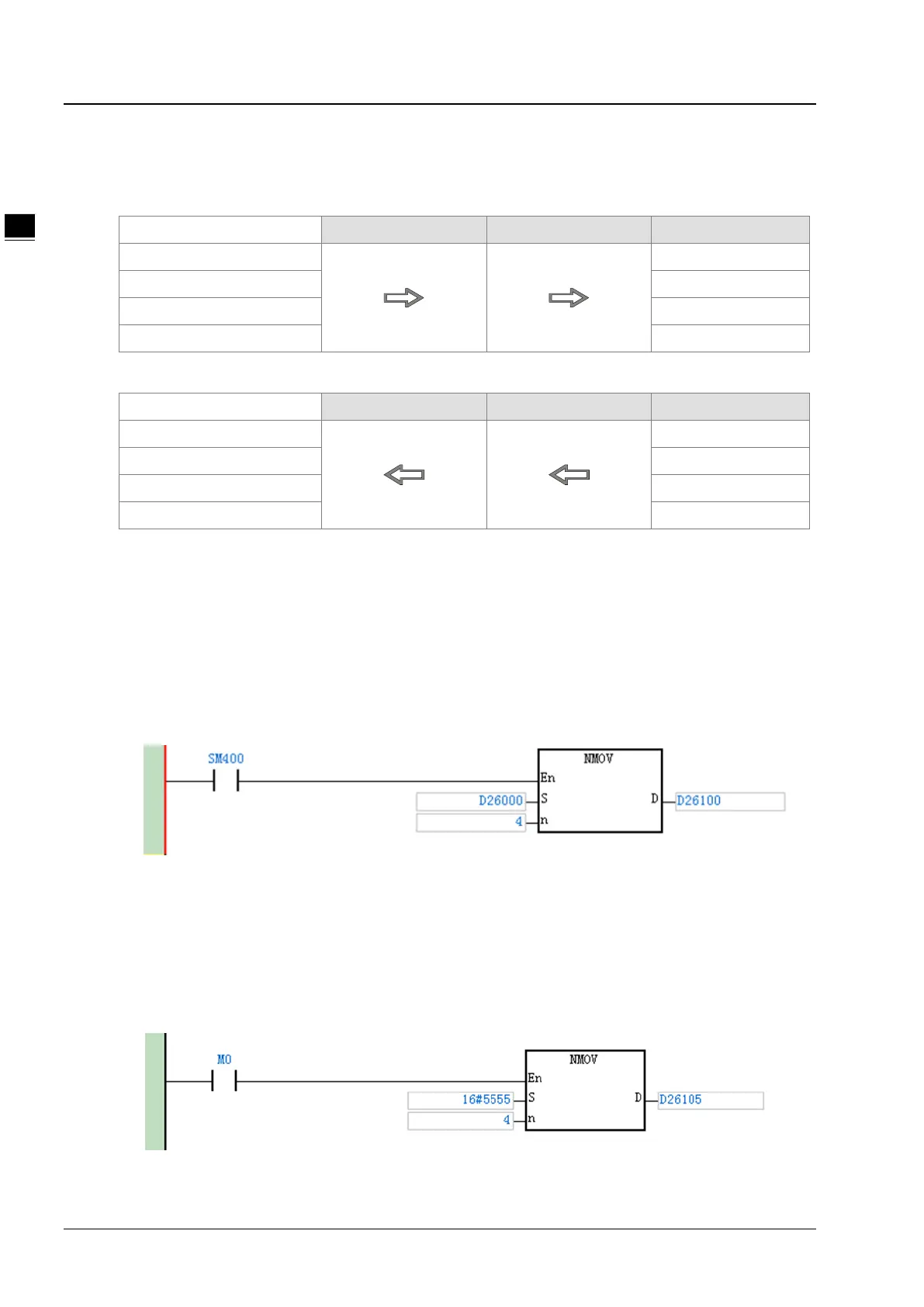
The program in the PLC connecting AS01DNET slave:
Program Explanation:
The contents in D26000~D26003 are the data received from the master and the contents in D26100~D26103
are the data transmitted to the master. SM400 is a normally open contact. The program above can make the
contents in D26000~D26003 move to D26100~D26103.
The program in the PLC connecting AS01DNET master:
 Loading...