Chapter 11 DeviceNet Master Scanner Module AS01DNET-A
11-53
1
11.5.3 Installation
11.5.3.1. Installing AS01DNET (in RTU Mode)
11.5.3.1.1. Connecting AS01DNET-A (in RTU Mode) and Extension Module on DIN Rail
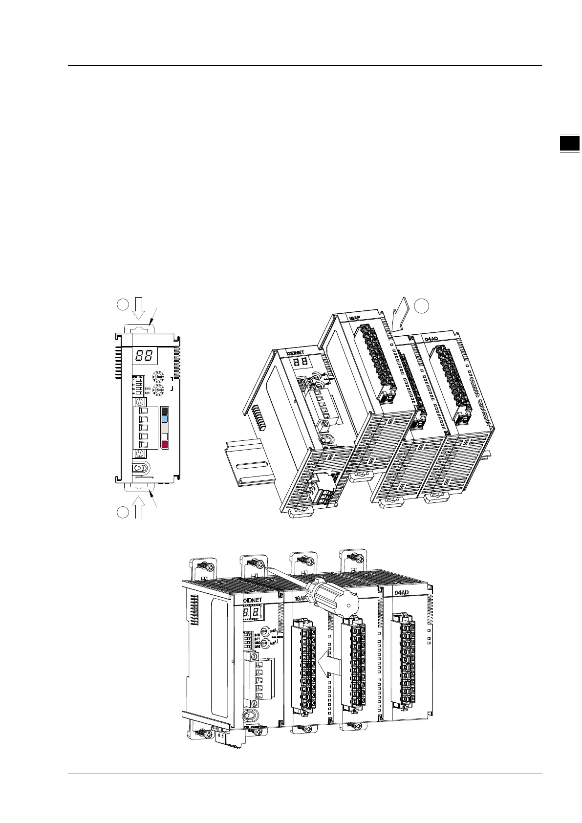
Please push the clips of AS01DNET-A (RTU) in the directions indicated by arrow ① until hearing a click. That
means the DIN clips are interlocked each other. Then insert the module hooks at the bottom into the DIN rail
mounting slot until hearing a click. That means AS01DNET-A (RTU) is connected to the DIN rail.
To install the second module AS16AP11T, push the clips of AS16AP11T in the direction indicated by arrow ①.
Then aim the left-side slot of AS16AP11T at the right-side slot of AS01DNET-A (RTU) and push AS16AP11T in
the direction as illustrated by arrow ② until hearing a click. That means the module is on the DIN rail and is
connected to AS01DNET-A (RTU). In the same way, install more IO modules on the right side of AS01DNET-A
(RTU) and DIN rail one by one.
01DN ET
MS
NS
x10
1
x10
0
IN 0
IN 1
Node Addres s
RTU Maste r Sla ve/
DIN rail clip
DIN rail clip
1
1
Tighten the screws on the top of the module at the end of installing.
 Loading...