AS Series Module Manual
11-6
11.2.5 Address Switch
The switch is used for setting up the node address of AS01DNET-A in DeviceNet network. Range: 00~63 (64~99
are forbidden.)
Switch setting Description
0 … 63 Valid DeviceNet node address
64…99 Invalid DeviceNet node address
Example: If users need to set the node address of AS01DNET-A to 26, simply switch the corresponding switch of
x101 to 2 and the corresponding switch of x100 to 6.
Note:
After the setup is completed, repower AS01DNET-A.
While AS01DNET-A is working, changing the setting of the node address is invalid.
Rotate the switch carefully with a slotted screwdriver to prevent damage to the switch.
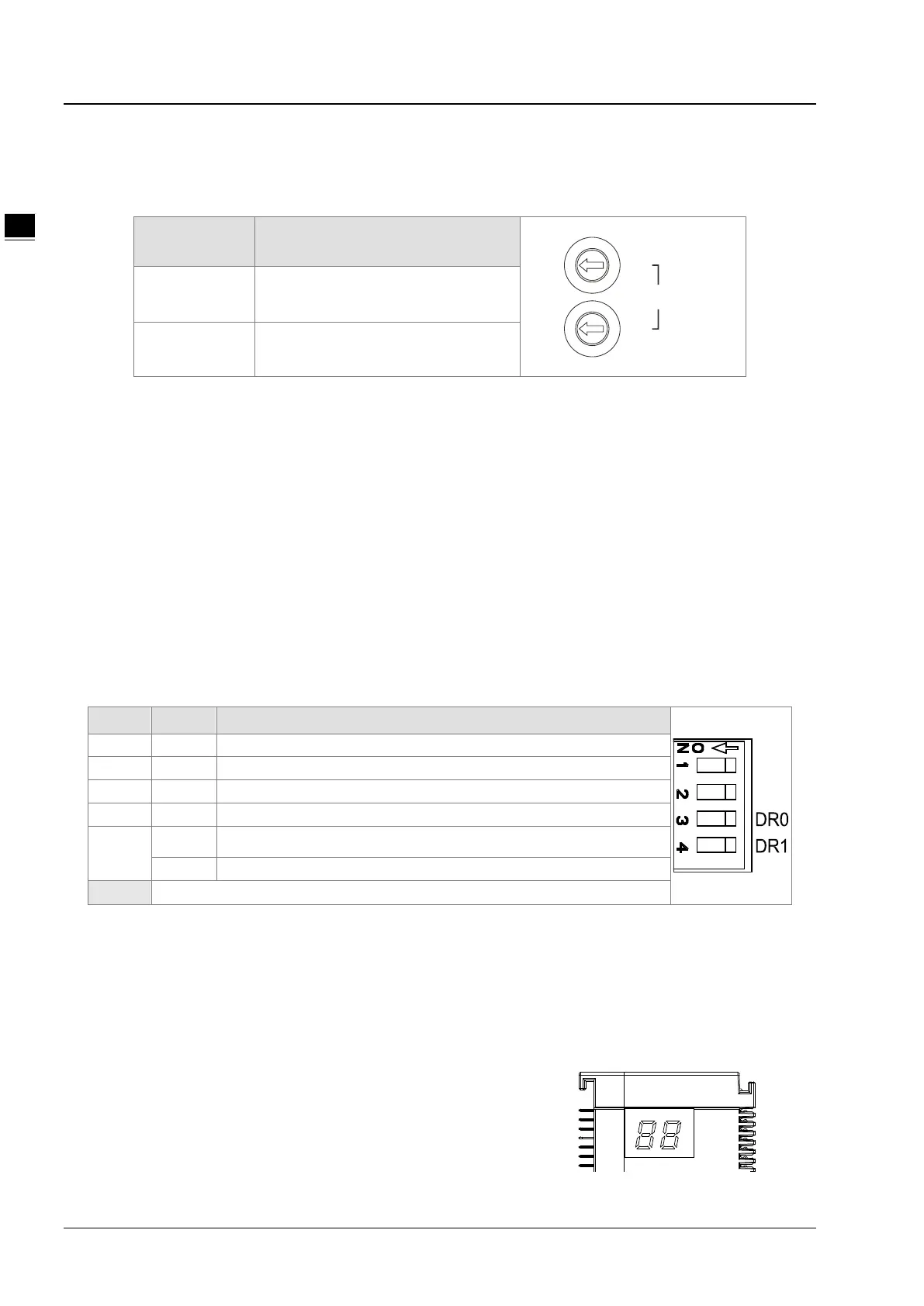
11.2.6 Function Switch
The function switches are used for:
Setting up the work mode (IN0)
Setting up the baud rate of DeviceNet network (DR0~DR1)
DR1 DR0 Baud Rate
Entering the mode of extended baud rate
IN0
ON When the slave is off-line, the I/O data in the buffer area will be held.
When the slave is off-line, the I/O data in the buffer area will be cleared.
Note:
After the setup of the function switch is completed during power off, repower AS01DNET-A.
While AS01DNET-A is working, changing the setting of the node address is invalid.
Adjust the DIP switch carefully with a slotted screwdriver to prevent any damage to the switch.
11.2.7 Digital Displayer
The digital displayer provides following functions:
Showing the node address of AS01DNET-A and error ID
Showing the error information about a slave
0
1
2
3
4
5
6
7
8
9
x10
1
Node Address
0
1
2
3
4
5
6
7
8
9
x10
0
 Loading...