Chapter 13 IO-Link Communication Module AS04SIL
13-37
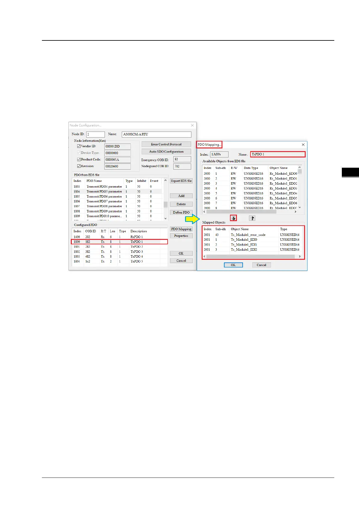
Each object in the EDS file is 1 word (2 bytes) in size and thus one PDO corresponds to one mapped register. Assign all
input parameters to available TxPDOs according to the parameters in the Normal Exchange Area of AS04SIL-A in
section 13.4.3. The mapped PDO object of the input process data is Tx_ModuleX_EDIY (Exchanging Data Input which is
referred to as EDI).
In this example, the AS04SIL-A module is the first one on the right of the RTU module. Therefore the value of X is 1 and
the PDO mapped object for error codes is Tx_Module1_error_code. The corresponding objects starts from
Tx_Module1_EDI0 as below.
Based on all communication port address information in the HWCONFIG 4.0 software in section 13.4.3, assign all input
process data to available TxPDOs, which corresponds to the mapped object Tx_NIOX_PD_InputZ and assign all output
process data to available RxPDOs, which corresponds to the mapped object Rx_NIOX_PD_OutputY.
In this example, the AS04SIL-A module is the first one on the right of the RTU module. Therefore the value of X is 1, the
input objects starting from Tx_NIO1_PD_Input0 correspond to IO-Link Port1~ Port4 in Process Data- Input respectively
and the output objects starting from Rx_NIO1_PD_Output0 correspond to IO-Link Port1~ Port4 in Process Data- Output
respectively.
Configure all parameters which need to be updated continuously (which are called objects in CANopen Builder) to one
TxPDO or RxPDO according to the steps described above. Add AS00SCM-A RTU to the slave list (Node List) and then the
real addresses of mapped registers in AS CPU show up immediately as below.
 Loading...