Parameters ASDA-B2-F
7-56 September, 2015
7
P4-05 JOG Servo Motor Jog Control
ddress: 040AH
040BH
Operational
Interface:
Panel / Software Communication
Related
Section:
4.4.2
Default: 20
Control
Mode:
ALL
Unit: r/min Range: 0 ~ 5000
Format: DEC Data Size: 16-bit
Settings:
Two control methods are as follows:
1. Operation Test
After the JOG speed is set by P4-05 via the panel, the panel will display the symbol of JOG.
Pressing the UP key can control JOG operation in positive direction; pressing the DOWN key can
control JOG operation in negative direction. Stop pressing to stop the JOG operation. If there is any
error in this setting, then the motor cannot operate. The maximum JOG speed is the maximum
speed of the servo motor.
2. Communication Control
1 ~ 5000: JOG speed 4998: JOG operation in CCW direction
4999: JOG operation in CW direction 0: Stop operation
Note:
When writing via communication, if the frequency is high, please set P2-30 to 5.
P4-06▲■ FOT Digital Output Register (Readable and Writable)
ddress: 040CH
040DH
Operational
Interface:
Panel / Software Communication
Related
Section:
4.4.3
Default: 0
Control
Mode:
ALL
Unit: - Range: 0 ~ 0xFF
Format: HEX Data Size: 16-bit
Settings:
bit 00: correspond to DO code=0x30 bit 08: correspond to DO code=0x38
bit 01: correspond to DO code=0x31 bit 09: correspond to DO code=0x39
bit 02: correspond to DO code=0x32 bit 10: correspond to DO code=0x3A
bit 03: correspond to DO code=0x33 bit 11: correspond to DO code=0x3B
bit 04: correspond to DO code=0x34 bit 12: correspond to DO code=0x3C
bit 05: correspond to DO code=0x35 bit 13: correspond to DO code=0x3D
bit 06: correspond to DO code=0x36 bit 14: correspond to DO code=0x3E
bit 07: correspond to DO code=0x37 bit 15: correspond to DO code=0x3F
If P2-18 is set to 0x0130, then DO#1 represents the bit 0 status of P4-06. DO code (0x30~0x3F) can
be set via communication DO, and then write into P4-06.
P4-07■ ITST Multi-function of Digital Input
ddress: 040EH
040FH
Operational
Interface:
Panel / Software Communication
Related
Section:
4.4.4, 8.2
Default: 0
Control
Mode:
ALL
Unit: - Range: 0 ~ 3FFF
Format: HEX Data Size: 16-bit
Settings:
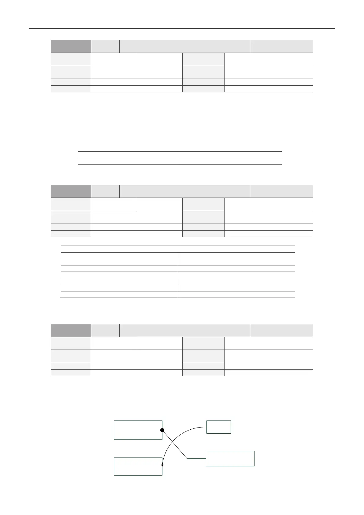
The DI input signal can come from external terminal (DI1 ~ DI5) or software SDI1 ~ 5 (Bit 0 ~ 4 of
P4-07) and is determined by P3-06. If the corresponding bit of P3-06 is 1, it means the source is
software SDI (P4-07); if the corresponding bit is 0, then the source is hardware DI. See the following
graph:
External DI: DI1 ~ DI5
Software DI,
SDI1~SDI5
(P4-07 bit)
P3-06
DI after combination
 Loading...


