ASDA-B2-F Parameters
September, 2015 7-57
Read parameters: shows the DI status after combination
Write parameters: writes the software SDI status (The function of this parameter is the same
whether it is written via panel or communication.)
Example: The value of reading P4-07 is 0x0011, which means DI1 and DI5 are ON; the value of
writing P4-07 is 0x0011, which means software SDI1 and SDI5 are ON
Please refer to P2-10 ~ P2-14 for function program of digital input pin DI (DI1~DI5).
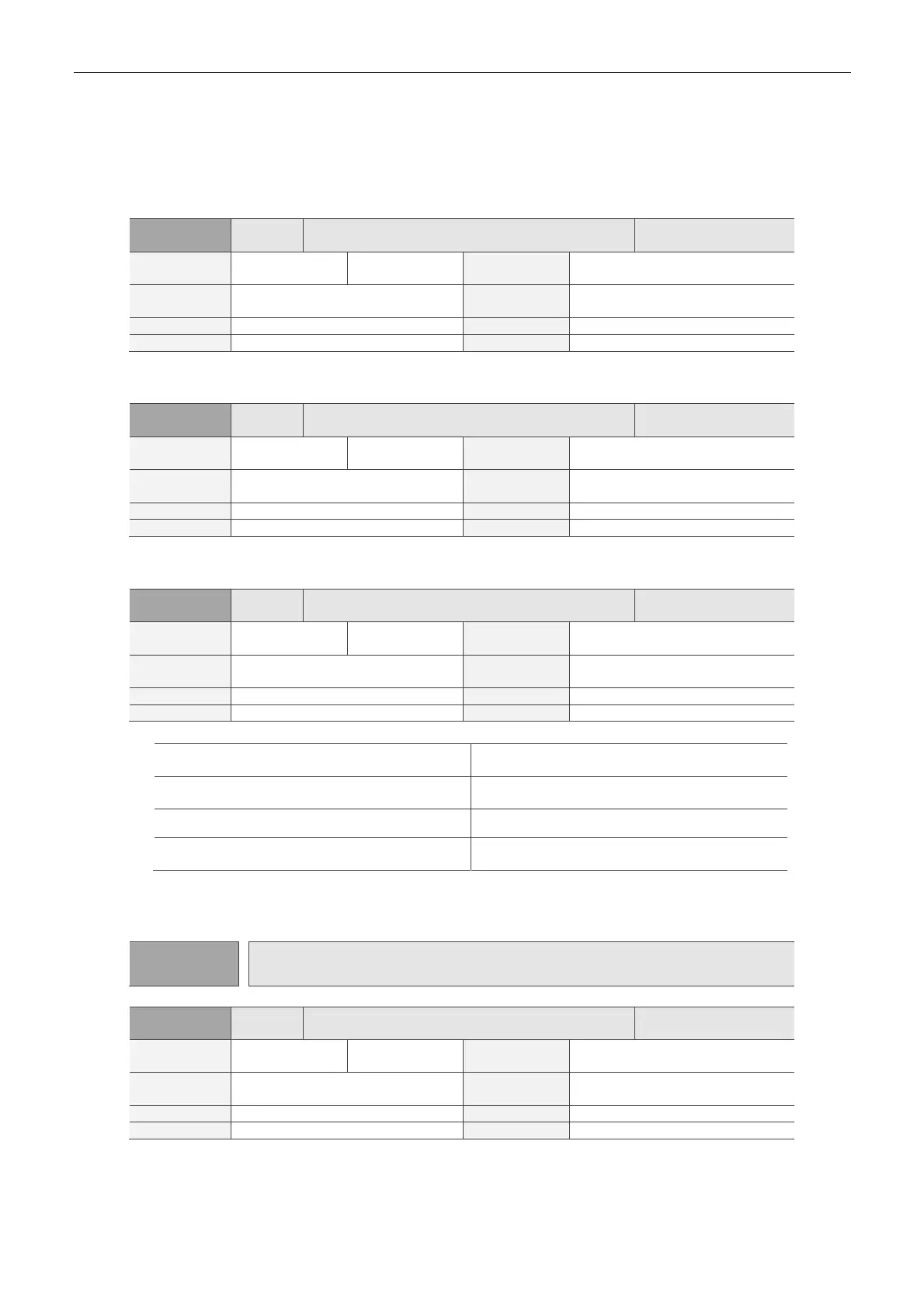
P4-08★
PKEY Input Status of the Drive Keypad (Read-only)
ddress: 0410H
0411H
Operational
Interface:
Panel / Software Communication
Related
Section:
-
Default: -
Control
Mode:
ALL
Unit: - Range: (Read-only)
Format: HEX Data Size: 16-bit
Settings:
The aim is to check if the five keys MODE, UP, DOWN, SHIFT and SET can work normally.
P4-09★
PKEY Digital Output Status (Read-only)
ddress: 0412H
0413H
Operational
Interface:
Panel / Software Communication
Related
Section:
4.4.5
Default: -
Control
Mode:
ALL
Unit: - Range: 0 ~ 0x1F
Format: HEX Data Size: 16-bit
Settings:
There is no difference between reading via panel or communication.
P4-10■ CEN Adjustment Selection
ddress: 0414H
0415H
Operational
Interface:
Panel / Software Communication
Related
Section:
-
Default: 0
Control
Mode:
ALL
Unit: - Range: 0 ~ 6
Format: DEC Data Size: 16-bit
Settings:
0: Reserved
4: Execute the adjustment of current detector (W
phase) hardware offset
1: Reserved
5: Execute the adjustment of 1 ~ 4 hardware
offset
2: Reserved 6: Execute the adjustment of IGBT ADC
3: Execute the adjustment of current detector (V
phase) hardware offset
-
Note:
The adjustment function needs to be enabled by the setting of parameter P2-08. When adjusting, the external
wiring which connects to torque needs to be removed completely and must be in Servo Off status.
P4-11~P4-14 Reserved
P4-15 COF1 Current Detector (V1 Phase) Offset Adjustment
ddress: 041EH
041FH
Operational
Interface:
Panel / Software Communication
Related
Section:
-
Default: Factory default
Control
Mode:
ALL
Unit: - Range: 0 ~ 32767
Format: DEC Data Size: 16-bit
Settings:
Manually adjust the hardware offset. The adjustment function needs to be enabled by the setting of
parameter P2-08. It is not suggested to adjust the auxiliary adjustment. This parameter cannot be
reset.
 Loading...


