ASDA-B2-F Parameters
September, 2015 7-63
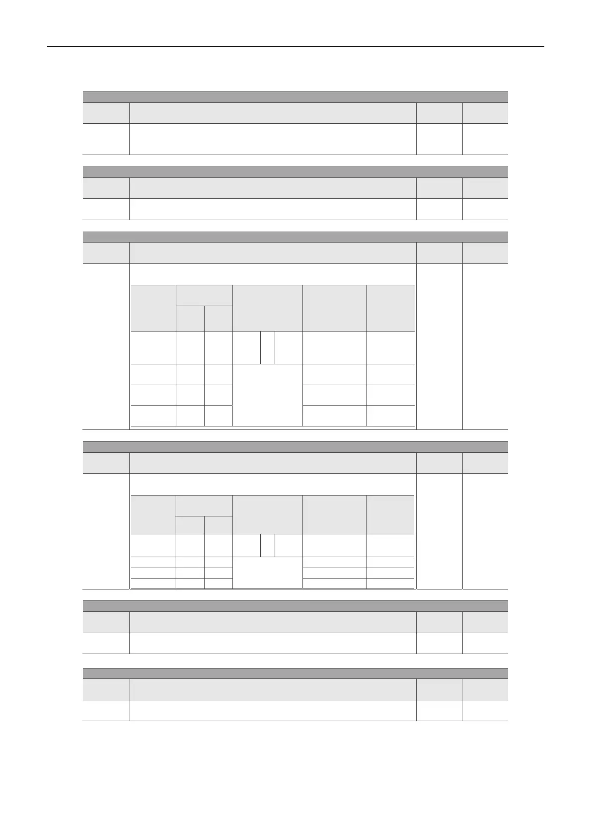
Table 7.1 Function Description of Digital Input (DI)
Setting Value: 0x02
DI Name Function Description of Digital Input (DI)
Trigger
Method
Control
Mode
ARST
After the cause of alarm has been removed, when this DI is ON, it
means the alarm shown on the servo drive has been cleared.
Rising
edge
triggered
ALL
Setting Value: 0x03
DI Name Function Description of Digital Input (DI)
Trigger
Method
Control
Mode
GAINUP
In speed and position modes, when this DI is ON (P2-27 should be set
to 1), the gain switches to the one multiplies the switching rate.
Level
triggered
DMCNET,
Sz
Setting Value: 0x14, 0x15
DI Name Function Description of Digital Input (DI)
Trigger
Method
Control
Mode
SPD0
SPD1
Internal Speed Command Selection (1~4)
Speed
Command
Number
DI Signal of
CN1
Command
Source
Content Range
SPD1 SPD0
S1 0 0 Mode Sz N/A
Speed
command is 0
0
S2 0 1
Internal Register
Parameter
P1-09
+/- 5000
r/min
S3 1 0 P1-10
+/- 5000
r/min
S4 1 1 P1-11
+/- 5000
r/min
Level
triggered
Sz
Setting Value: 0x16, 0x17
DI Name Function Description of Digital Input (DI)
Trigger
Method
Control
Mode
TCM0
TCM1
Internal Torque Command Selection (1~4)
Torque
Command
Number
DI Signal of
CN1
Command
Source
Content Range
TCM1
TCM0
T1 0 0 Mode
Tz
N/A
Torque
command is 0
0
T2 0 1
Internal Register
Parameter
P1-12 +/- 300 %
T3 1 0 P1-13 +/- 300 %
T4 1 1 P1-14 +/- 300 %
Level
triggered
Tz
Setting Value: 0x21
DI Name Function Description of Digital Input (DI)
Trigger
Method
Control
Mode
EMGS When this DI is ON, the motor stops urgently.
Level
triggered
ALL
Setting Value: 0x22
DI Name Function Description of Digital Input (DI)
Trigger
Method
Control
Mode
NL
(CWL)
Reverse inhibit limit (contact b)
Level
triggered
ALL

 Loading...


