ASDA-B2-F Wiring
September, 2015 3-9
3
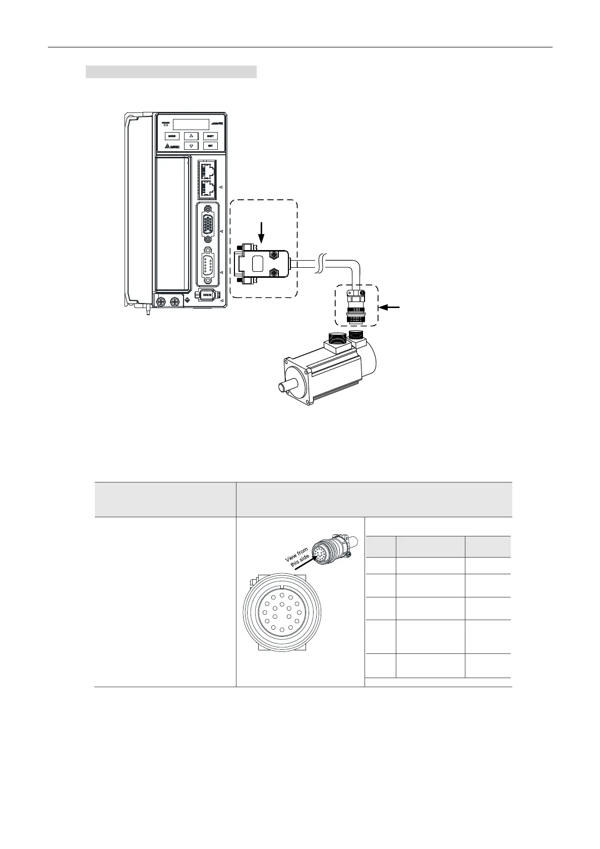
Encoder Connection (Diagram 2):
Servo Drive
Servo Motor
Connector of
Encoder Cable
CN2 Connector
Military
Connector
*1
C
N
1
C
N
2
C
N
3
C
N
6
Note:
This diagram shows the connection between the servo drive and the motor encoder, which is not drawn by
the practical scale. The specification will change subject to the selected servo drive and motor model.
1. Please refer to Section 3.4, CN2 Connector.
Motor Model
Connector of Encoder Cable
ECMA-G△1303S (300 W)
ECMA-E△1305S (500 W)
ECMA-G△1306S (600 W)
ECMA-F△1308S (850 W)
ECMA-G△1309S (900 W)
ECMA-C△1010S (1000 W)
ECMA-E△1310S (1000 W)
ECMA-F△1313S (1300 W)
ECMA-E△1315S (1500 W)
ECMA-F△1318S (1800 W)
ECMA-C△1020S (2000 W)
ECMA-E△1320S (2000 W)
ECMA-C△13304 (3000 W)
ECMA-E△1820S (2000 W)
A
E
B
D
C
HF
G
L
K
J
M
N
P
RS
T
Military Connector
Pin
No.
Terminal
Identification
Color
A
T+ Blue
B T -
Blue&
Black
S DC+5V
Red/Red&
White
R GND
Black/
Black&
White
L
BRAID
SHIELD
–
Please select shielded multi-core and the shielded cable should connect to the SHIELD end.
Please refer to the description of Section 3.1.6.
Note:
1. Box, () in servo motor model represents brake or keyway / oil seal.
2. Triangle, (
△
) in servo motor model represents encoder type. Please refer to Chapter 1 for detail.

 Loading...


