CI
ACI circuit
internal circuit
Figure 6-18
Impedance: 250Ω
Range: 0–20mA / 4–20mA / 0–10V = 0–Max.
Output Frequency (Pr. 01-00)
ACI Switch, factory setting is 4–20mA
AUI
Auxiliary analog voltage input
ACM
AUI
+10V
-10V
(-10V~+10V)
in
Figure 6-19
Impedance: 20kΩ
Range: -10–+10V
DC
=0–Max. Output Frequency
(Pr. 01-00)
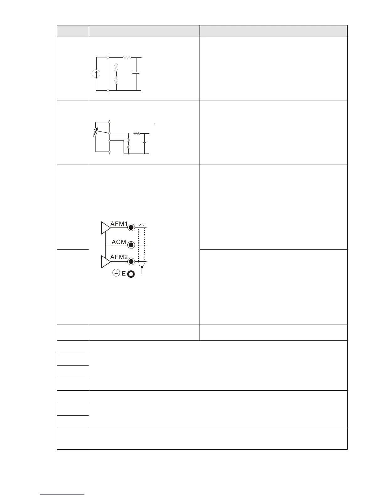
AFM1
Multi-function analog voltage output
Figure 6-20
0–10V Max. output current 2mA, Max. load 5kΩ
-10–10V maximum output current 2mA, maximum
load 5kΩ
Output current: 2mA max
Resolution: 0–10V corresponds to Max. operation
frequency
Range: 0–10V -10–+10V
AFM1 Switch, factory setting is 0–10V
AFM2
0–10V Max. output current 2mA, Max. load 5kΩ
0–20mA Max. load 500Ω
Output current: 20mA max
Resolution: 0–10V corresponds to Max. operation
frequency
Range: 0–10V 4–20mA
AFM2 Switch, factory setting is 0–10V
ACM Analog signal common Common for analog terminals
STO1
Default setting is shorted
Power removal safety function for EN954-1 and IEC/EN61508
When STO1–SCM1; STO2–SCM2 is activated, the activation current is 3.3mA ≥ 11V
DC
Note: Please refer to CH 17 Safe Torque off Function.
SCM1
STO2
SCM2
SG+
MODBUS RS-485
Note: Please refer to CH12 DESCRIPTION OF PARAMETER SETTINGS group 09
Communication Parameters for more information.
SG-
SGND
RJ-45
PIN 1, 2, 7, 8: Reserved PIN 3, 6: SGND
PIN 4: SG- PIN 5: SG+
Table 6-1
NOTE: Wire size of analog control signals: 0.75 mm
2
[18 AWG] with shielded wire
 Loading...


