Chapter 6 Control TerminalsC2000
6-8
Terminals Terminal Function Factory Setting (NPN mode)
MI1
–
MI8
Multi-function input 1–8
Refer to parameters 02-01–02-08 to program the
multi-function inputs MI1–MI8.
Source mode
ON: the activation current is 3.3 mA ≥ 11 V
DC
OFF: cut-off voltage ≤ 5 V
DC
Sink Mode
ON: the activation current is 3.3 mA ≤ 13 V
DC
OFF: cut-off voltage ≥ 19 V
DC
DFM
Digital frequency meter
DFM
DCM
Figure 6-15
Regard the pulse voltage as the output monitor
signal; Duty-cycle: 50 %
Min. load impedance: 1 kΩ / 100 pf
Max. current: 30 mA
Max. voltage: 30 V
DC
DCM Digital frequency signal common
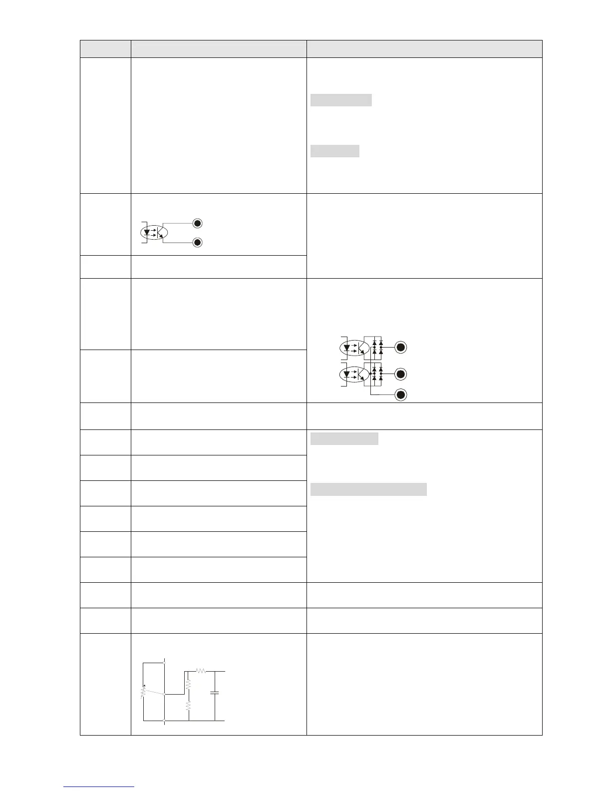
MO1
Multi-function output 1
(photocoupler)
The AC motor drive releases various monitor
signals, such as drive in operation, frequency
attained and overload indication, via transistor
(open collector).
MO1
MO2
MCM
Figure 6-16
MO2
Multi-function output 2
(photocoupler)
MCM Multi-function output common Max 48 V
DC
50 mA
RA1 Multi-function relay output 1 (N.O.) a
Resistive Load
3A (N.O.) / 3A (N.C.) 250 V
AC
5A (N.O.) / 3A (N.C.) 30 V
DC
Inductive Load (COS 0.4)
1.2A (N.O.) / 1.2A (N.C.) 250 V
AC
2.0A (N.O.) / 1.2A (N.C.) 30 V
DC
It is used to output each monitor signal, such as
drive is in operation, frequency attained or
overload indication.
RB1 Multi-function relay output 1 (N.C.) b
RC1 Multi-function relay common
RA2 Multi-function relay output 2 (N.O.) a
RB2 Multi-function relay output 2 (N.C.) b
RC2 Multi-function relay common
+10V Potentiometer power supply Analog frequency setting: +10V
DC
20 mA
-10V Potentiometer power supply Analog frequency setting: -10V
DC
20 mA
AVI
Analog voltage input
ACM
AVI
+10V
AVI circuit
internal circuit
Figure 6-17
Impedance: 20 kΩ
Range: 0–20 mA / 4–20 mA / 0–10 V = 0–Max.
Output Frequency (Pr.01-00)
AVI switch, factory setting is 0–10 V