Chapter 6 Control TerminalsC2000
6-7
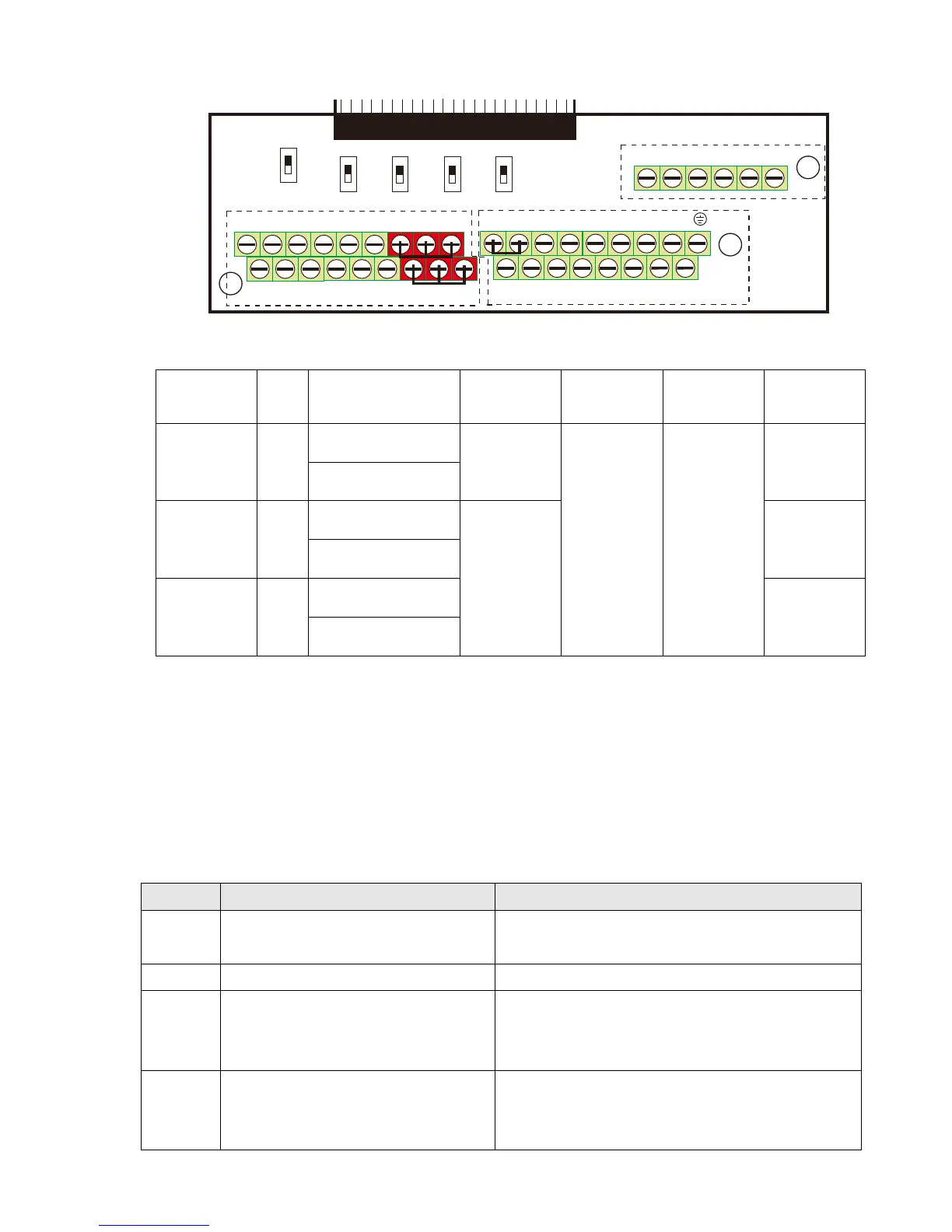
6-2 Specifications of Control Terminal
MI1
+
24 V C OM FWD
MO1
MI5MI3
ACI+1 0V AVI
A F M1 MO 2
MCM
MI 7
MI4DC M RE V MI 2 MI 8MI6ACM-10V AU IAFM2
DFM
SG-SG+
RA2RC2RB2 RB1RC1 RA1
0-10V
-10 -10V
0-10V 0-10V
0-10V
0-20mA
0-2 0m A
0 -20mA Open
120
AFM1
AFM2
AVI
A CI 485
SGND
STO 1 S TO 2
SCM1SCM2D CM
+24V
B
A
C
Figure 6-14. Removable Terminal Block
Function
name
Area Conductor
Stripping
length
(mm)
Maximum
Wire Gauge
Minimum
Wire Gauge
Tightening
torque
(±10)
RELAY
Terminals
Ⓐ
Conductor cross
section solid wire
4–5
1.5 mm²
[16 AWG]
0.2 mm²
[26 AWG]
5 kg-cm
[4.3 lb-in.]
[0.49 Nm]
Conductor cross
section stranded wire
Control
Terminals
Ⓑ
Conductor cross
section solid wire
6–7
8 kg-cm
[6.9 lb-in.]
[0.78 Nm]
Conductor cross
section stranded wire
Control
Terminals
Ⓒ
Conductor cross
section solid wire
2 kg-cm
[1.7 lb-in.]
[0.20 Nm]
Conductor cross
section stranded wire
Wiring precautions:
In the figure above, the factory setting for STO1, STO2, +24V and SCM1, SCM2, DCM are short
circuit. The +24V from section Ⓒ of above figure is for STO only, and cannot be used for other
purposes. The factory setting for +24V-COM is short circuit and SINK mode (NPN); please refer
to Chapter 4 Wiring for more detail.
Tighten the wiring with slotted screwdriver:
Ⓐ Ⓑ is 3.5 mm (wide) x 0.6 mm (thick); Ⓒ is 2.5 mm (wide) x 0.4 mm (thick)
When wiring bare wires, make sure they are perfectly arranged to go through the wiring holes.
Terminals Terminal Function Factory Setting (NPN mode)
+24V
Digital control signal common
(Source)
+24V 5% 200 mA
COM Digital control signal common (Sink) Common for multi-function input terminals
FWD
Forward-Stop command
FWD-DCM:
ON
forward running
OFF
deceleration to stop
REV Reverse-Stop command
REV-DCM:
ON
reverse running
OFF
deceleration to stop
 Loading...


