Chapter 7 Optional AccessoriesC2000
7-117
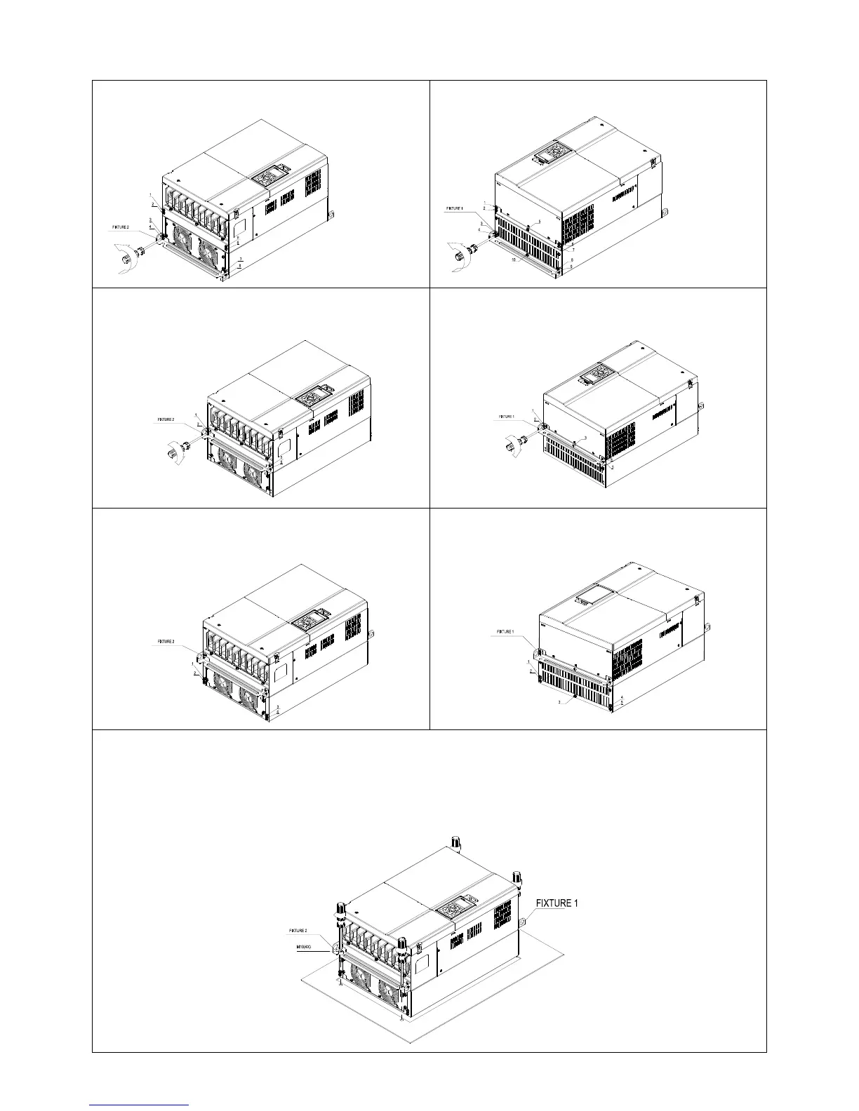
Frame D0 & D & E
1. Loosen 8 screws and remove Fixture 2 (as shown in
the following figure).
2. Loosen 10 screws and remove Fixture 1 (as shown
in the following figure).
3. Fasten 4 screws (as shown in the following figure).
Screw torque: 30~32 kg-cm / [26.0~27.8 Ib-in.] /
[2.9~3.1 Nm].
4. Fasten 5 screws (as shown in the following figure).
Screw torque: 30~32 kg-cm / [26.0~27.8 Ib-in.] /
[2.9~3.1 Nm]
5. Fasten 4 screws (as shown in the following figure).
Screw torque: 24~26 kg-cm / [20.8~22.6 Ib-in.] /
[2.4~2.5 Nm]
6. Fasten 5 screws (as shown in the following figure).
Screw torque: 24~26 kg-cm / [20.8~22.6 Ib-in.] /
[2.4~2.5 Nm]
7. Place 4 screws (M10) through Fixture 1 & 2 and the plate then fasten the screws. (as shown in the following
figure)
Frame D0/D M10*4
Screw torque: 200~240 kg-cm / [173.6~208.3 Ib-in.] / [19.6~235 Nm]
Frame E M12*4
Screw torque: 300~400 kg-cm / [260~347 Ib-in.] / [29.4~39.2 Nm]
 Loading...


