Chapter 8 Option CardsC2000
8-22
8-9 EMC-PG01U / EMC-PG02U
-- PG card (ABZ Incremental encoder signal/ UVW Hall position signal input)
1. FSW1 S: Standard UVW Output Encoder; D: Delta Encoder
2. When using the Delta Encoder, wait for at least 250ms after powering up to receive signals from
UVW. If a running command is received before UVW signals finish, a PGF5 error message will be
given. So wait for 250ms before sending a running command.
3. EMC-PG02U has encoder disconnection detection function.
8-9-1 Terminal descriptions
Set by Pr.10-00–10-02, Pr.10-16–10-18
Terminals Descriptions
PG1
VP
Output voltage for power: +5V/+12V5% (use FSW3 to
switch +5V/+12V)
Max. output current: 200mA
DCM
Common for power and signal
A1, /A1, B1, /B1, Z1, /Z1
Encoder input signal (Line Driver)
It can be 1-phase or 2-phase input.
Max. output frequency: 300kHz
U1, /U1, V1, /V1, W1, /W1
Encoder input signal
PG2
A2, /A2,
B2, /B2
Pulse Input signal (Line Driver or Open Collector)
Open Collector Input Voltage: +5–+24V (Note1)
It can be 1-phase or 2-phase input.
Max. output frequency: 300kHz.
PG OUT
AO, /AO, BO, /BO, ZO,
/ZO
, SG
PG Card Output signals.
It has division frequency function: 1–255 times
Max. output voltage for Line driver: 5V
DC
Max. output current: 15mA
Max. output frequency: 300kHz
SG is the GND of PG card. It is also the GND of position
machine or PLC to make the output signal to be the
common pivot point.
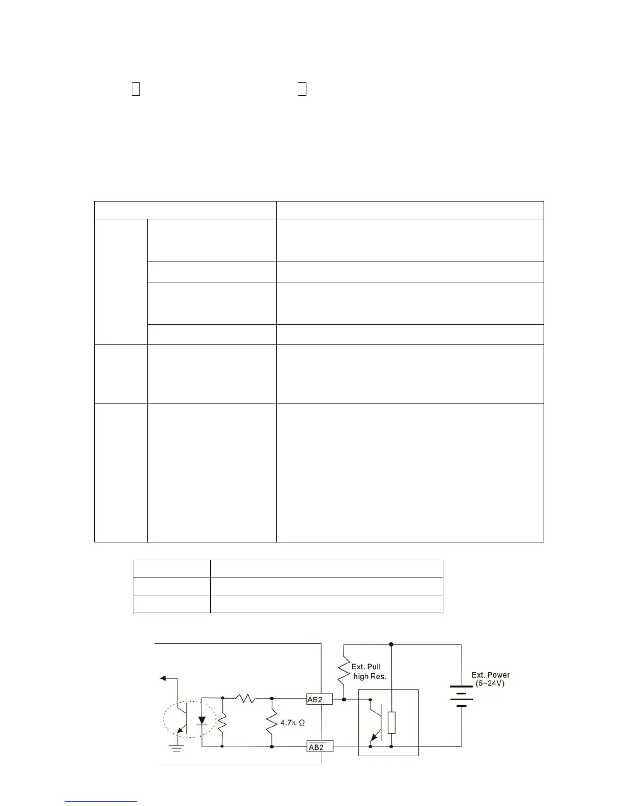
Note 1: Open Collector application, input current 5–15mA to each set then each set needs one pull-up resistor.
5V
Recommended pull-up resistor: above100–220, 1/2W
12V
Recommended pull-up resistor: above 510–1.35k, 1/2W
24V
Recommended pull-up resistor: above1.8k–3.3k, 1/2W
PG2 Wiring Diagram
 Loading...


