Chapter 12 Description of Parameter SettingsC2000
12.1-02-9
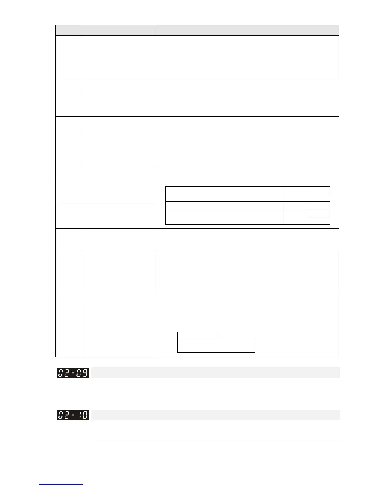
Settings Functions Descriptions
45
Forward direction homing
(PL)
Signal input for forward direction limit switch (PL). ON: the drive
uses the settings in Pr.00-40, 00-41, 00-42 to execute homing in
a forward direction (clockwise).
Note: PL means input terminal detection is positive-edge
triggered or is regarded as N.C. (Normally Closed)
46
Homing (ORG)
ORG point input. ON: the drive uses the setting in Pr.00-40,
00-41, 00-42 to execute homing.
47
Enable homing function
Pr.00-10=3 (homing mode), if the external terminal MIx=47 is
OFF, the drive ignores the HOME command and executes Point-
to-Point position control.
48
Mechanical gear ratio
switch
ON: the mechanical gear ratio switches to the second group.
Refer to Pr.10-04–Pr.10-07.
49 Enable drive
When the drive is enabled, the RUN command is valid.
When the drive is disabled, the RUN command is invalid.
When the drive is operating, the motor coasts to stop.
This function varies with MOx=45.
50
Slave dEb action to
execute
Slave receives dEb message from Master, avoids low voltage of
DC BUS, and coast to stop because of Lv error.
51
Selection for PLC mode
bit0
PLC status bit1 bit0
Disable PLC function (PLC 0) 0 0
Trigger PLC to operation (PLC 1) 0 1
Trigger PLC to stop (PLC 2) 1 0
No function 1 1
52
Selection for PLC mode
bit1
53
Trigger CANopen quick
stop
When this function is enabled under CANopen control, it will
change to quick stop. Refer to Chapter 15 CANopen overview for
more details.
55 Brake release
This parameter needs to be used with Pr. 02-56. The main
purpose is to make sure if mechanical brake works or not after
triggering brake release command.
If the action is right, mechanical brake will give signal to MI
terminal.
Please check time sequence chart for reference.
56
Local / Remote Selection
Use Pr. 00-29 to select for LOCAL/ REMOTE mode (refer to Pr.
00-29).
When Pr. 00-29 is not set to 0, on the digital keypad KPC-CC01 it
will display LOC/ REM status. (It will display on the KPC-CC01 if
the firmware version is above version 1.021).
bit0
REM 0
LOC 1
UP/DOWN Key Mode
Default: 0
Settings 0: UP / DOWN by acceleration / deceleration time
1: UP / DOWN constant speed (Pr. 02-10)
Constant speed. The Accel. / Decel. Speed of the UP/ DOWN Key
Default: 0.001
Settings 0.001~1.000Hz/ms
Use when the multi-function input terminals are set to 19, 20 (UP / DOWN command). The
frequency increases or decreases according to Pr.02-09 and Pr.02-10.
 Loading...


