Chapter 12 Description of Parameter SettingsC2000
12.1-10-9
If entering the low magnetic area and the input voltage (or DC BUS) plummets (e.g. an unstable
power net causes instant insufficient voltage, or a sudden load that makes DC BUS drop), which
causes the ACR diverge and oc, then increase the gain. If the Id value of a spur creates large
noise in high-frequency output current, decrease the gain to reduce the noise. Decrease the gain
will slow down the response.
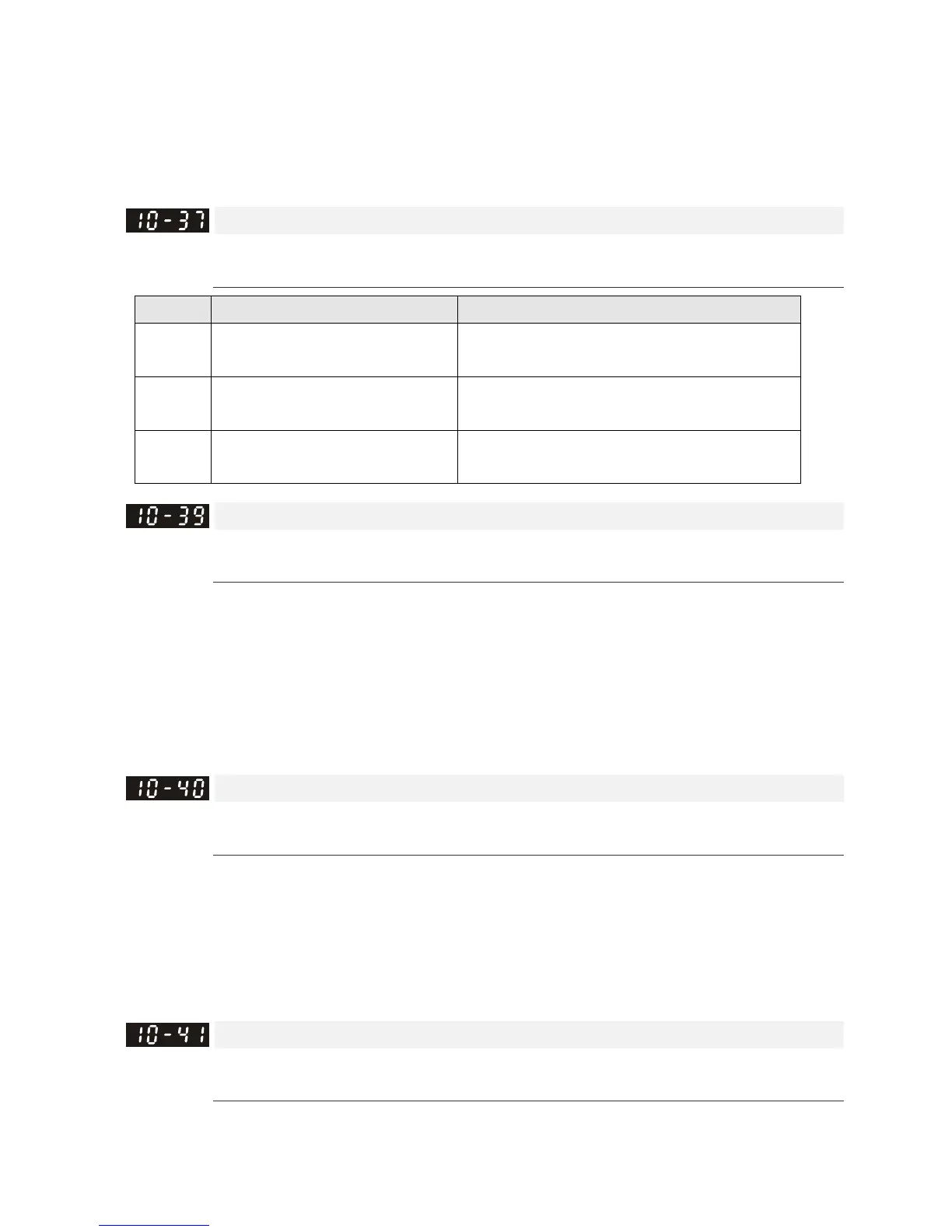
PM Sensorless Control Word
Default: 0000h
Settings 0000–FFFFh
bit No. Function Description
2 Choose a control mode to start.
0: Start in IF mode
1: Start in VF mode
3 Choose a mode to stop.
0: Stop in IF mode
1: Stop in VF mode
5 Choose a control mode to stop
0: When lower than Pr. 10-40, coast to stop
1: When lower than Pr. 10-40, ramp to stop
Frequency Point to Switch from I/F Mode to PM Sensorless Mode
Default: 20.00
Settings 0.00–599.00Hz
Sets the frequency for the switch point from low frequency to high frequency.
If the switch point is too low, the motor does not generate enough back-EMF to let the speed
estimator measure the rotor right position and speed, and causes stall and oc when running at
the switch point frequency
If the switch point is too high, the active area of I/F is too wide, which generates more current and
cannot save energy. If the current value for Pr. 10-31 is too high, the high switch point makes the
drive continue to output with the setting value for Pr. 10-31.
Frequency Point to Switch from PM Sensorless Mode to I/F Mode
Default: 20.00
Settings 0.00–599.00Hz
Sets the switch point from high frequency to low frequency.
If the switch point is too low, the motor does not generate enough back-EMF to let the speed
estimator measure the rotor right position and speed when running at the switch point frequency.
If the switch point is too high, the active area of I/F is too wide, which generates more current and
cannot save energy. If the current of Pr. 10-31 is too high, the high switch point makes the drive
continue to output with the setting value for Pr. 10-31).
I/F Mode, Id Current Low Pass-Filter Time
Default: 0.2
Settings 0.0–6.0 sec.
Sets the filter time for Pr. 10-31. Smoothly increases the magnetic field to the current command
setting value under the I/F mode.
 Loading...


