Chapter 16 PLC Function ApplicationsC2000
16-17
Device type Description of Function
Data register
When a PLC is used to perform various types of sequence control and set time
value and count value control, it most commonly perform data processing and
numerical operations, and data registers are used exclusively for storage of data
and various parameters. Each data register contains 16 bits of binary data, which
means that it can store one word. Two data registers with adjacent numbers can
be used to process double words.
Device indicated as: D0, D1 to D399, etc. The device is expressed as the
symbol "D" , and its order is expressed as a decimal number.
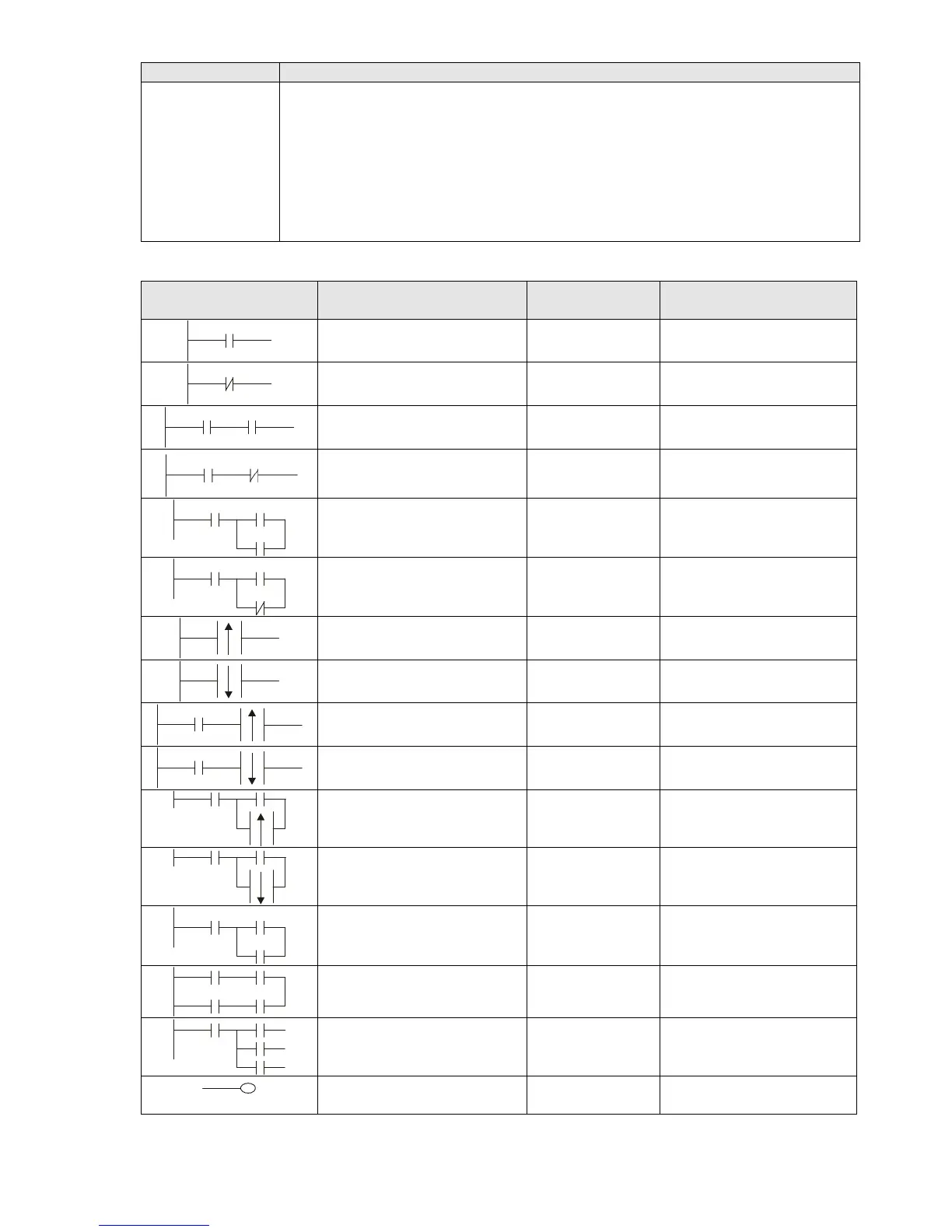
Ladder diagram images and their explanation
Ladder diagram
structures
Explanation of commands Command Using Device
NO switch, contact a LD
X、Y、M、T、C
NC switch, contact b LDI
X、Y、M、T、C
Series NO AND
X、Y、M、T、C
Series NC ANI
X、Y、M、T、C
Parallel NO OR
X、Y、M、T、C
Parallel NC ORI
X、Y、M、T、C
Positive edge-triggered
switch
LDP
X、Y、M、T、C
Negative edge-triggered
switch
LDF
X、Y、M、T、C
Positive edge-triggered
series
ANDP
X、Y、M、T、C
Negative edge-triggered
series
ANDF
X、Y、M、T、C
Positive edge-triggered
parallel
ORP
X、Y、M、T、C
Negative edge-triggered
parallel
ORF
X、Y、M、T、C
Block series ANB N/A
Block parallel ORB N/A
Multiple outputs
MPS
MRD
MPP
N/A
Coil driven output
commands
OUT
Y、M

 Loading...


