27
Installation and Operation Manual for RPI M6A M8A M10A inverters V1.0 2016-02-03
5 Planning the installation
5.8 DC connection
NOTICE
Machine and equipment damage may occur.
Exceeding the maximum current per DC input
can cause an overheating of the DC inputs.
► Always consider the maximum current of the
DC inputs when planning the installation.
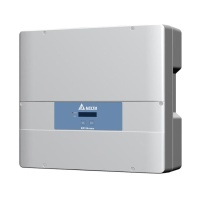
5.8.1 Symmetrical and asymmetrical power input
The inverter operates using two separate MPP trackers that can
handle both symmetrical and asymmetrical power input. This
allows you to set up complex PV system designs. For example:
east/west-facing roof (asymmetric load) or a south facing roof
(symmetrical load).
7:00 13:00 19:00
kW
Total
East Roof
West Roof
East
West
Fig. 5.12: Concept of 2-MPP-tracker system for asymmetrical
power input
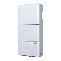
The following gures explain how symmetrical and asymmetrical
power input is handled:
Symmetrical power input
I
max
U
max
U
startup
Input Current
Input Voltage
Max. Power MPPT Range
Input Current DC 1
Input Current DC 2
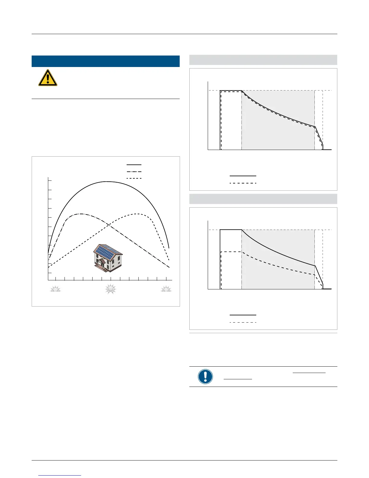
Asymmetrical power input
I
max
U
max
U
startup
Input Current
Input Voltage
Max. Power MPPT Range
Input Current DC 1
Input Current DC 2
Fig. 5.13: I-U curve for symmetrical and asymmetrical power
input (schematic diagrams)
For currents and voltages see “13. Technical
data”, p. 113.

 Loading...