33
Installation and Operation Manual for RPI M6A M8A M10A inverters V1.0 2016-02-03
5 Planning the installation
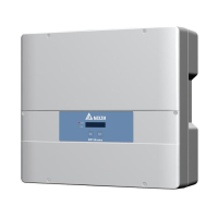
a) 12 V
DC
supply power from communication card type 2
Use a voltmeter to check which terminal on the plug is VCC.
GND
VCC
VCC plug Dry contacts plug
Strobe light Buzzer
Fig. 5.19: Providing a 12 V
DC
supply power for an external
alarm device from the communication card, variant 1
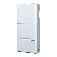
GND
VCC
VCC plug
Dry contacts plug
Strobe light Buzzer
Fig. 5.20: Providing a 12 V
DC
supply power for an external
alarm device from the communication card, variant 2
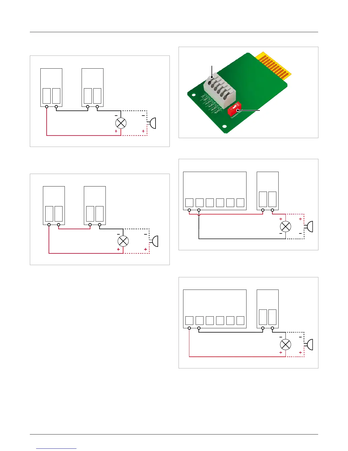
b) 12 V
DC
supply power from RS485 card
Terminal block for
RS485 and VCC
DIP switch for RS485
termination resistor
Terminal block for
RS485 and VCC
DIP switch for RS485
termination resistor
Fig. 5.21: RS485 card
GND
VCC
DATA+
DATA-
DATA+
DATA-
RS485 terminal block Dry contacts plug
Strobe light Buzzer
Fig. 5.22: Providing a 12 V
DC
supply power for an external
alarm device from the RS485 card, variant 1
GND
VCC
DATA+
DATA-
DATA+
DATA-
RS485 terminal block Dry contacts plug
Strobe light Buzzer
Fig. 5.23: Providing a 12 V
DC
supply power for an external
alarm device from the RS485 card, variant 2

 Loading...