59
Installation and Operation Manual for RPI M6A M8A M10A inverters V1.0 2016-02-03
6 Installation
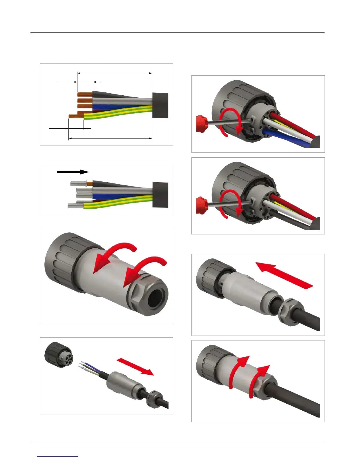
1. Remove the cable sheath as shown and remove 12 mm of
insulation from each wire end. Do not twist wire ends as this
reduces the surface contact area with the wire end sleeve
(bootlace pin).
12 mm
52.5 mm
12 mm
55 mm (PE)
2. Place a wire end sleeve on each wire end and crimp them on
tightly.
3. Unscrew the nut and cable housing from the socket insert.
4. Slide nut (1) and housing (2) over the cable.
(2)
(1)
5. Slide the wires of the AC cable into the terminals of the pin
insert and screw them tight with the hex-wrench (recom-
mended torque 2.5 Nm). Observe the correct phase se-
quence when doing this.
The rst image shows wiring for a 4-wire system (3P4W), the
second one for a 3-wire system (3P3W).
6. Slide all parts into the pin insert and fasten the cable housing
and the nut. Tighten the nut and the cable housing.

 Loading...