Chapter 3 Profile and Parts
3-3
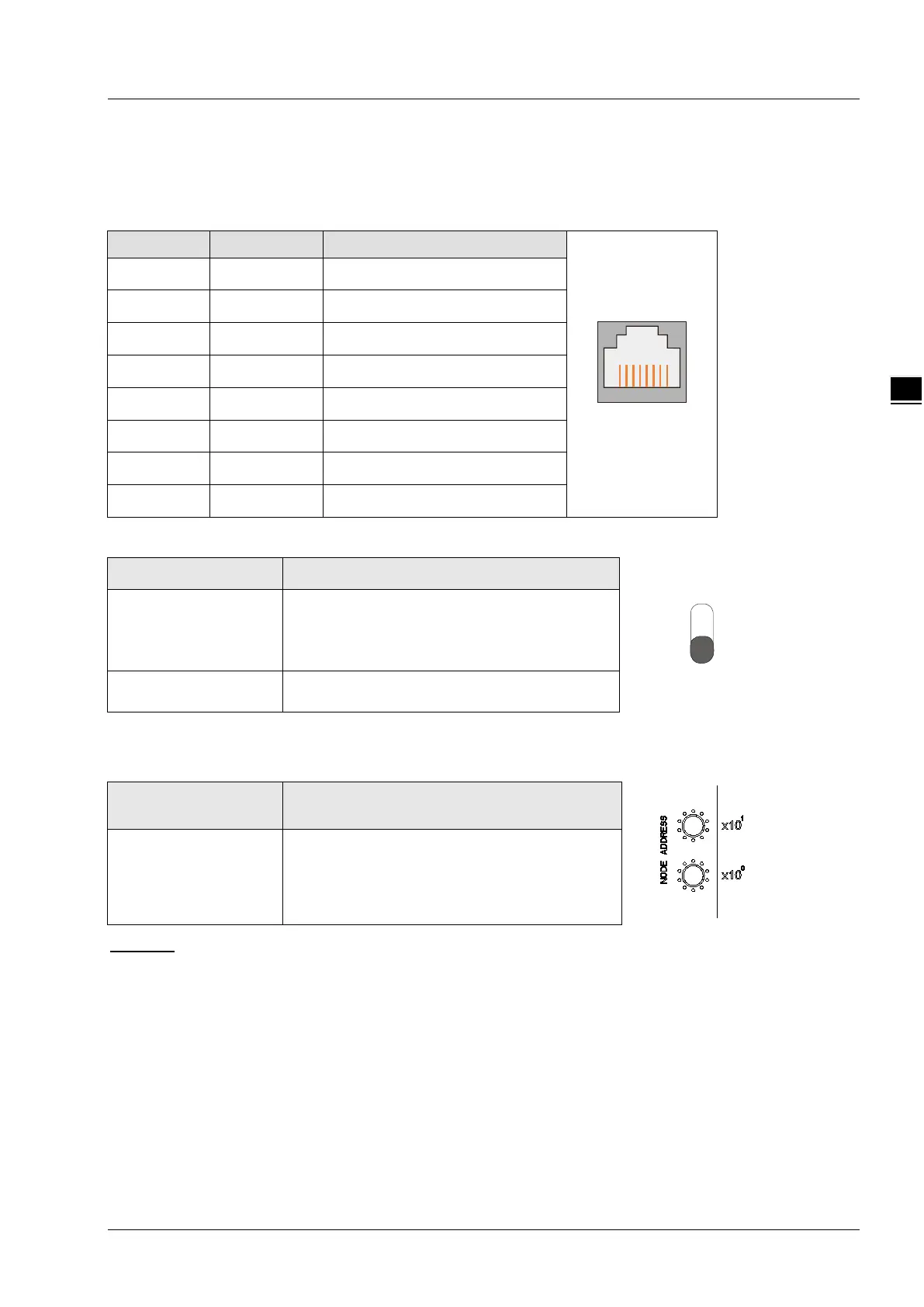
3.3 EtherCAT Port
EtherCAT port is used for the EtherCAT communication.
See the following table for the definitions of pins.
PIN Signal Description
1 Tx+ Positive pole for transmitting data
2 Tx- Negative pole for transmitting data
3 Rx+ Positive pole for receiving data
4
Reserved Reserved
5
Reserved Reserved
6 Rx- Negative pole for receiving data
7
Reserved Reserved
8
Reserved Reserved
3.4 RUN/STOP Switch
RUN/STOP switch Description
STOP → RUN
1. To re-detect the number of extension
modules and digital points.
2. To read/write the data in the extension
RUN → STOP
To stop reading/writing the data in the extension
module.
3.5 Address Switches
The switches are used for setting up the node address of RTU-ECAT on EtherCAT network.
Switch setting Description
0 ~ 99 EtherCAT node address
Example:
If you need to set the node address of RTU-ECAT to 26, simply switch the corresponding switch of x10
1
to
2 and the corresponding switch of x10
0
to 6.
Notes:
Please set up the node address when the power is switched off. After the setup is completed, re-power
RTU-ECAT.
When RTU-ECAT is operating, changing the setting of the node address will be invalid.
Use the slotted screwdriver to rotate the switch carefully in case the switch is scratched.