Wiring the Inverter
Inverter
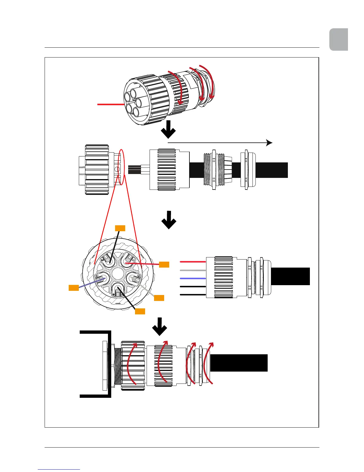
Next tighten the cable gland body ➁ to connector housing ➀ and the
cable gland cap ➂ to the cable gland body ➂. Tightening torque for
cable sheath diameters between 22 and 32 mm: 6 to 8 Nm. Rotate
the coupling ring ➃ to mate the connector with the inverter‘s AC plug.
After wiring the mating connector, screw the
connector housing ➀ to the coupling ring ➃. To
do this push the coupling ring ➃ to the connec-
tor housing ➀ and tighten 1-2 Nm.
Rotate the connector housing ➀ and cable
gland body ➁ and cable gland cap ➂ to
remove them from the coupling ring.
The female cable
connector needs to
be wired as shown
below.
To wire the connector refer to placement
of L1, L2, L3, N and PE shown to the left.
Screw termination is provided to x the
wires to the contacts.
NOTE: Rear
view of cable
connector
L1
L2
L3
N
PE
Cable
Slide the connector housing, cable gland
body and cable gland cap onto the cable.
L3
L1
L2
N
 Loading...