Figures
Figure 2.1.: Solar Inverter System Operation Illustration . . . . . . . . . . . . . 26
Figure 3.1.: Unpacking Process . . . . . . . . . . . . . . . . . . . . . . . . . . 29
Figure 3.2.: The Type Label 10 TL and 15 TL . . . . . . . . . . . . . . . . . . . 30
Figure 3.3.: The Type Label 20 TL and 30 TL . . . . . . . . . . . . . . . . . . . 30
Figure 4.1.: Dimensions of SOLIVIA 10 TL . . . . . . . . . . . . . . . . . . . . 31
Figure 4.2.: Dimensions of SOLIVIA 15 TL / 20 TL / 30 TL . . . . . . . . . . . . 32
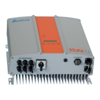
Figure 4.3.: 10 TL Inverter Exterior View. . . . . . . . . . . . . . . . . . . . . .33
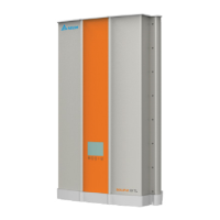
Figure 4.4.: 15 TL / 20 TL / 30 TL Inverter Exterior View. . . . . . . . . . . . . .34
Figure 4.5.: Grounding Kit . . . . . . . . . . . . . . . . . . . . . . . . . . . . . 34
Figure 4.6.: LCD Display and Control Panel . . . . . . . . . . . . . . . . . . . .35
Figure 4.7.: Input/Output Interface . . . . . . . . . . . . . . . . . . . . . . . . .36
Figure 4.8.: Air Outlet Illustration . . . . . . . . . . . . . . . . . . . . . . . . . 37
Figure 4.9.: Fan Control 10 TL. . . . . . . . . . . . . . . . . . . . . . . . . . .37
Figure 4.10.: Fan Control 15 TL and 20 TL . . . . . . . . . . . . . . . . . . . . . 38
Figure 4.11.: Fan Control 30 TL. . . . . . . . . . . . . . . . . . . . . . . . . . .38
Figure 5.1.: SOLIVIA 10 TL, 15 TL, 20 TL, 30 TL protection classes . . . . . . . 40
Figure 5.2.: Attaching the mounting bracket to the wall . . . . . . . . . . . . . . 41
Figure 5.3.: Correct and Incorrect Installation Illustration . . . . . . . . . . . . . 42
Figure 5.4.: Proper Installation Gap . . . . . . . . . . . . . . . . . . . . . . . . 43
Figure 5.5.: Derating curve for 10 TL, 15 TL, 20 TL and 30 TL . . . . . . . . . . 44
Figure 6.1.: Connection of system if DC inputs are oating . . . . . . . . . . . . 46
Figure 6.2.: Connection of system with Positive Ground or Negative Ground. . .47
Figure 6.3.: AC cable stripping requirements for 10 TL, 15 TL, and 20 TL . . . . 49
Figure 6.4.: AC plug sealing ring for AC connector 10 TL, 15 TL, and 20 TL . . . 50
Figure 6.5.: AC connector 10 TL, 15 TL, and 20 TL . . . . . . . . . . . . . . . . 51
Figure 6.6.: AC cable stripping requirements for 30 TL . . . . . . . . . . . . . . 52
Figure 6.7.: AC connector for 30 TL . . . . . . . . . . . . . . . . . . . . . . . . 53
Figure 6.8.: Input/Output Interface . . . . . . . . . . . . . . . . . . . . . . . . .55
Figure 6.9.: DC Wiring Illustration . . . . . . . . . . . . . . . . . . . . . . . . . 56
Figure 6.10.: Comparison diagram of Balanced Power Input and Unbalanced
Power Input . . . . . . . . . . . . . . . . . . . . . . . . . . . . . . 57
Figure 6.11.: SOLIVIA 10 TL Efciency Curve . . . . . . . . . . . . . . . . . . . 58
Figure 6.12.: SOLIVIA 15 TL Efciency Curve . . . . . . . . . . . . . . . . . . . 59
 Loading...