0044-0391-0M Rev F y solo Series Owner’s Manual
5
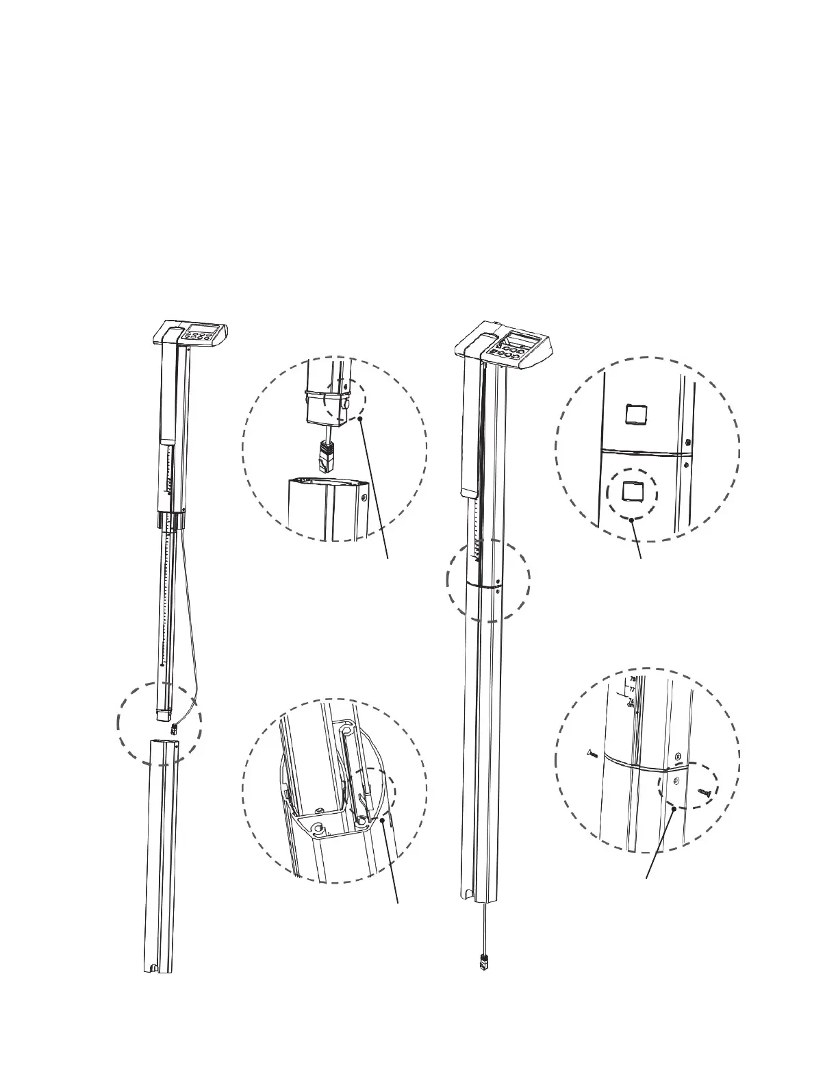
Scale Assembly, Cont.
Step 2
1. Align Part 3 (lower outside column) with assembled Part 1 and 2 (display upper outside
and inside column, and lower inside column).
2. Press the locking tab (on Part 2, lower inside column) inward and then insert it into
Part 3 (lower outside column).
3. Slide the cable connector through Part 3 (lower outside column).
4. Press Part 3 and Part (1 and 2) together until the locking tab snaps in place.
5. Ensure that the locking tab is locked securely.
6. Install the (2) M3 x 12 machine screws (one on each side of Part 3) to secure Part 1 and
2 together with Part 3.
Figure No. 3
(Scale Assembly, Step 2)
c
g
d
e
f
Ensure locking tab
is securely locked.
Press locking tab
inward to insert
Part 2 into Part 3.
Slide the cable
connector
through Part 3.
Install (1) M3 x 12
screw on each
side of Part 3.