User Manual DEV 1953
Copyright DEV Systemtechnik GmbH 2015-2017 137
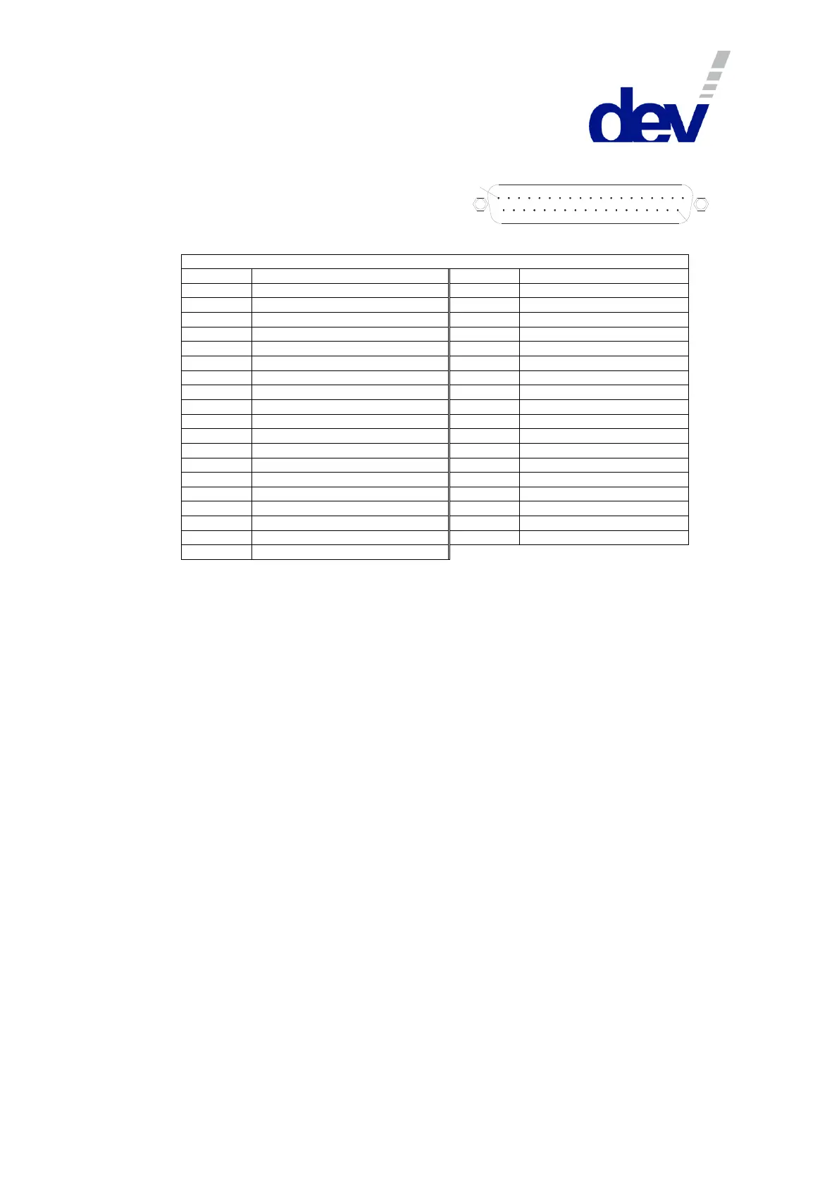
Digital Interface Connector (Options 56 & 57)
Connector: Sub-D 37 (male)
Connector screws: UNC 4-40
Digital Interface Connector
Output: Module 1 (normally open)
Output: Module 2 (normally open)
Output: Module 3 (normally open)
Output: Module 4 (normally open)
Output: Module 5 (normally open)
Output: Module 6 (normally open)
Output: Module 7 (normally open)
Output: Module 8 (normally open)
Output: Module 9 (normally open)
Output: Module 10 (normally open)
Output: Module 11 (normally open)
Output: Module 12 (normally open)
Output: Module 13 (normally open)
Output: Module 14 (normally open)
Output: Module 15 (normally open)
Output: Module 16 (normally open)
Output: Module 16 (normally closed)
Note:
• Please refer to chapters 3.1.4, 3.2.26, & 5.4 for more information on the digital interface.
• The digital outputs (pins 1…17) are realized as dry relay contacts, pins 18 and 19 are the common pins
(Out_Common).
If a contact is open, it means that the corresponding module is switched to the primary input port ("In A"). If it
is closed (i.e. it has the same electrical potential as the common pins), the module is switched to the
secondary input port ("In B"). An exception is pin 17 that indicates the status of module 16 as a normally
closed contact, i.e. contradictory to pin 16.
• The digital inputs (pins 20…35) are realized with optocouplers with pins 36 & 37 as the common ground pins
(In_Common).
If the device is switched (from Local Mode or Auto Mode) to Remote Mode with Individual switching mode
activated and if no voltage is applied to a digital input, the corresponding module is switched to the primary
input port ("In A"). On the other hand, if a positive electrical potential (Option 56: nominal +24 V, 5.8 mA and
Option 57: nominal +12 V, 4.8 mA) is applied to a digital input, the corresponding module is switched to the
secondary input port ("In B").
If the device is switched to Remote Mode with Simultaneous switching mode activated, the potential on the
digital input of the first member of a group determines the switch position of the group.
If the device is in Remote Mode and Individual switching mode is activated, a rising slope on a digital input
forces the corresponding module to be switched to the secondary input port ("In B"); a falling slope switches
the module to the primary input port ("In A").
If the device is in Remote Mode and Simultaneous switching mode is activated, a rising slope on any (!) digital
input assigned to a module being member of a group forces the corresponding group to be switched to the
secondary input port ("In B"). A falling slope on any digital input assigned to a member of a group switches the
group to the primary input port ("In A").